Method of constructing data center switching network and node apparatus
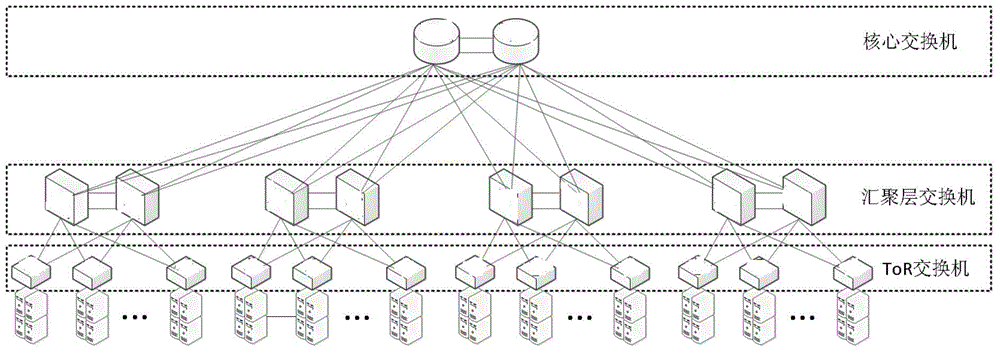
A technology for switching networks and data centers, applied in the field of building data center switching networks, methods and node devices, can solve problems such as increased chip energy consumption, time delay deterioration, and impact on upper-layer application performance, and achieve simple wiring, high interconnection bandwidth and Effect of Average Latency
- Summary
- Abstract
- Description
- Claims
- Application Information
AI Technical Summary
Benefits of technology
Problems solved by technology
Method used
Image
Examples
Embodiment 1
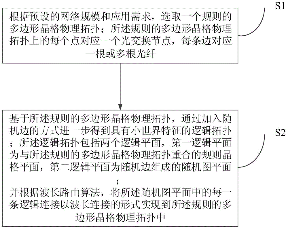
[0048] Such as image 3 As shown, the embodiment of the present invention provides a method for constructing a data center switching network, including:
[0049] S1. According to the preset network scale and application requirements, select a regular polygonal lattice physical topology; each point on the regular polygonal lattice physical topology corresponds to an optical switching node, and each edge corresponds to one or more root fiber;
[0050] S2. Based on the regular polygonal lattice physical topology, a logical topology with small-world characteristics is further obtained by adding random edges; the logical topology includes two logical planes, the first logical plane is a polygon with the regular A regular lattice plane where the physical topology of the lattice coincides, and the second logical plane is a random graph plane composed of random edges;
[0051] And according to the wavelength routing algorithm, implement each logical connection in the random graph pl...
Embodiment 2
[0071] Such as Figure 5 As shown, the embodiment of the present invention also provides a node device for constructing a data center switching network, and the node device includes several demultiplexing modules, a random graph plane optical switching processing module, a regular lattice plane optical switching processing module, several a multiplexing module, and an electrical packet switching module;
[0072] Wherein, the optical fiber is decomposed into multiple wavelengths after passing through the demultiplexing module, and a part of the wavelengths is input to the random graph plane optical switching processing module, and then output to the multiplexing module after being processed by adding and dropping; the other part of the wavelengths is input to the regular lattice plane optical switching processing module, and output to the multiplexing module after being processed by adding and dropping;
[0073] The electrical packet switching module implements electrical doma...
Embodiment 3
[0081] The present invention is described below by specific embodiment:
[0082] Such as Figure 6 As shown, taking the physical topology of a hexagonal lattice as an example, each solid line in the figure represents an optical fiber, and each point represents a node device described in the present invention. The signal transmission in the optical fiber is unidirectional. To simplify the discussion, it is assumed that there are at least three available wavelengths, namely λ1, λ2 and λ3. Among them, λ1 is used to provide a ring data bus in each cell, and each cell can be regarded as an independent optical burst switching ring network. λ2 and λ3 belong to the wavelength resources used to build the topological plane of the random graph. Here, the two wavelength connections of λ2 and λ3 are bidirectional. This is to ensure that the data round-trip and return delays are as consistent as possible when two nodes that are far away are interconnected through a random graph plane.
...
PUM
 Abstract
Description
Claims
Application Information
 - R&D
- Intellectual Property
- Life Sciences
- Materials
- Tech Scout
- Unparalleled Data Quality
- Higher Quality Content
- 60% Fewer Hallucinations
Browse by: Latest US Patents, China's latest patents, Technical Efficacy Thesaurus, Application Domain, Technology Topic, Popular Technical Reports.
© 2025 PatSnap. All rights reserved.Legal|Privacy policy|Modern Slavery Act Transparency Statement|Sitemap|About US| Contact US: help@patsnap.com


