Integrated stamping equipment

A kind of stamping equipment and integrated technology, applied in the field of stamping equipment, can solve the problems of manpower handling, easy punching and cooling

Inactive Publication Date: 2015-09-09
昆山—邦泰汽车零部件制造有限公司
View PDF8 Cites 5 Cited by
  • Summary
  • Abstract
  • Description
  • Claims
  • Application Information

AI Technical Summary

Problems solved by technology

[0002] Mounting holes need to be set on the parts, which need to be punched out by a punch, and then punched and deburred by a deburring device. In the prior art, the parts are punched collectively, and then transported to the deburring device for centralized processing and deburring , such a production line requires manpower to carry, and it is easy to punch and cool during the process of carrying, so it is no longer the best time for deburring. There is no one in the prior art that can save manpower and improve work efficiency. Integrated stamping equipment

Method used


Image

  • Integrated stamping equipment

Examples


Embodiment Construction

[0017] The present invention will be specifically introduced below in conjunction with the accompanying drawings and specific embodiments.

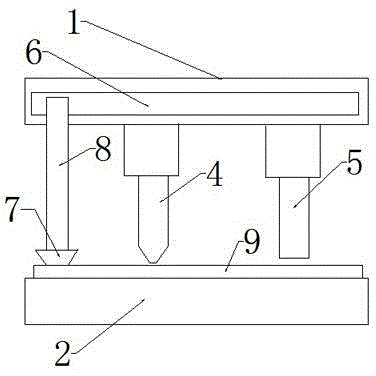
[0018] Integrated stamping equipment, including: upper stamping seat 1, lower stamping seat 2 for placing products, punching device 4 for upper stamping seat 1, deburring device 5 for upper stamping seat 1, fixed on upper stamping seat 1 and transported The delivery device for the part 9 to the position of the above-mentioned punching device 4 and the deburring device 5; the delivery device includes: a suction part that absorbs the part 9, and a moving part that is fixed on the upper stamping seat 1 and drives the suction part to move; as a preference, The moving part is a guide rail 6, and the suction part is a vacuum suction cup 7. The integrated stamping equipment also includes: a motor connected to the moving part and the suction part, and a controller connected to the motor. In order to allow the guide rail 6 to transport the parts ...


PUM


Abstract

The invention discloses integrated stamping equipment. The integrated stamping equipment comprises an upper stamping seat, a lower stamping seat used for placing a product, a punching device located onto the upper stamping seat, a deburring device located onto the upper stamping seat and a conveying device fixed onto the upper stamping seat and used for conveying a part to positions of the above punching device and of the deburring device. The conveying device comprises a suction part for sucking up the part and a movable part which is fixed onto the upper stamping seat and drives the suction part to move. The integrated stamping equipment has following beneficial effects: the integrated stamping equipment is capable of automatically conveying the part to a punch press for punching and then conveying the part to the deburring device for stamping and deburring without manpower; and the integrated stamping equipment, with punching and deburring functions, has high stamping quality and obtains effects of saving manpower and increasing working efficiency.

Description

technical field [0001] A punching device, especially a punching device. Background technique [0002] Mounting holes need to be set on the parts, which need to be punched out by a punch, and then punched and deburred by a deburring device. In the prior art, the parts are punched collectively, and then transported to the deburring device for centralized processing and deburring , such a production line requires manpower to carry, and it is easy to punch and cool during the process of carrying, so it is no longer the best time for deburring. There is no one in the prior art that can save manpower and improve work efficiency. Integrated stamping equipment. Contents of the invention [0003] In order to solve the deficiencies of the prior art, the object of the present invention is to provide a punching machine that automatically transports parts to a punching machine for punching, and then transports them to a deburring device for stamping and deburring. The process does not...

Claims


Application Information

Patent Timeline
Patent Type & Authority Applications(China)
IPC IPC(8): B21D35/00B21D43/18
Inventor 郑坚雄
Owner 昆山—邦泰汽车零部件制造有限公司
Why Eureka
Try Eureka