
Punching calibration workbench

A technology of workbench and calibration plate, which is applied in the direction of manufacturing tools, metal processing equipment, feeding devices, etc., and can solve the problems such as easy deviation of stamping parts

Inactive Publication Date: 2016-06-22
KUNSHAN YIBANGTAI AUTO PART MFG CO LTD
View PDF9 Cites 4 Cited by
  • Summary
  • Abstract
  • Description
  • Claims
  • Application Information

AI Technical Summary

Problems solved by technology

[0002] In the prior art, the stamping dies all adjust the position of the stamping part, so as to complete multiple stampings at different positions of the stamping part. In such a process, the position of the stamping part is prone to deviation, and it is necessary to adjust the position of the stamping part with the required stamping point. Calibration, thereby improving the product qualification rate, the existing technology has not yet solved such problems

Method used


Image

  • Punching calibration workbench
  • Punching calibration workbench

Examples


Embodiment Construction

[0019] The present invention will be specifically introduced below in conjunction with the accompanying drawings and specific embodiments.

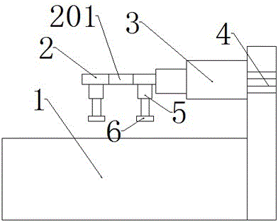
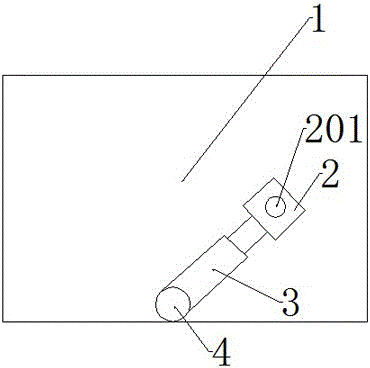
[0020] Stamping calibration workbench 1, comprising: a calibration plate 2 placed on the workbench 1, a telescopic piece fixed to the calibration plate 2, a rotating piece fixed to the telescopic piece, a pressure plate fixed under the calibration plate 2 and used to compress the workpiece to be stamped Tight assembly; the calibration plate 2 is provided with a calibration through hole 201, and the stamping head passes through the calibration through hole 201.

[0021] The compression assembly includes: a telescopic compression piece placed on both sides of the calibration through hole 201, and a buffer pad 6 placed under the telescopic compression piece. As a preference, the telescopic pressing part is the first electronic telescopic rod 5; the buffer pad 6 is a plastic foam pad or a rubber pad. In order to prevent the parts to be stamp...


PUM


Abstract

The invention discloses a punching calibration workbench. The punching calibration workbench comprises a calibration plate, a telescopic part, a rotary part and a tight-pressing assembly. The calibration plate is arranged on the punching calibration workbench and fixed through the telescopic part. The rotary part id fixed to the telescopic part. The tight-pressing assembly is fixed under the calibration plate and used for tightly pressing a to-be-punched part. The calibration plate is provided with a calibration through hole. A punching head penetrates through the calibration through hole. The punching calibration workbench provided by the invention is used for calibrating a punching part and making the punching part be aligned with a punching point. The punching calibration workbench can extend to any positions of the to-be-punched part, so that the to-be-punched part is calibrated fast and conveniently, and accordingly the product pass rate is increased. According to the punching calibration workbench, in order to achieve the effect that the to-be-punched part does not move in the punching process, the tight-pressing assembly is arranged under the calibration plate, so that accurate punching is ensured, and the punching quality is improved. In addition, the punching calibration workbench is simple in structure and low in cost.

Description

technical field [0001] A calibration device, in particular a calibration device suitable for stamping dies. Background technique [0002] In the prior art, the stamping dies all adjust the position of the stamping part, so as to complete multiple stampings at different positions of the stamping part. In such a process, the position of the stamping part is prone to deviation, and it is necessary to adjust the position of the stamping part with the required stamping point. Calibration, thereby improving the product qualification rate, the prior art has not yet solved such a problem. Contents of the invention [0003] In order to solve the deficiencies of the prior art, the purpose of the present invention is to provide a calibration device for calibrating whether the stamping part is aligned with the stamping point. The calibration device can be extended to any position of the stamping part, so that the stamping part can be obtained quickly and conveniently Calibration, the...

Claims


Application Information

Patent Timeline
Patent Type & Authority Applications(China)
IPC IPC(8): B21D43/00B21D22/02
CPCB21D43/003B21D22/02
Inventor 郑坚雄
Owner KUNSHAN YIBANGTAI AUTO PART MFG CO LTD
Learn More