Polarization light irradiation apparatus
A technology of illuminating device and polarized light, which is applied in the direction of lighting device, parts of lighting device, cooling/heating device of lighting device, etc., can solve the problem of uneven illumination and achieve the effect of improving uneven illumination
- Summary
- Abstract
- Description
- Claims
- Application Information
AI Technical Summary
Problems solved by technology
Method used
Image
Examples
no. 1 approach >
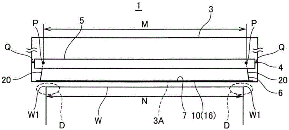
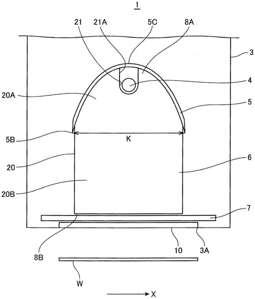
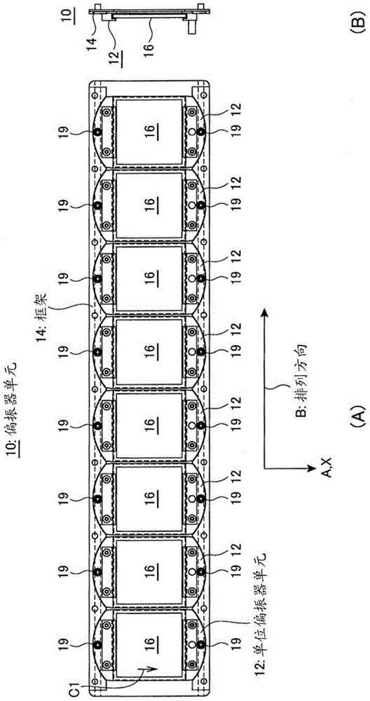
[0040] figure 1 is a front view schematically showing the polarized light irradiation device according to the first embodiment, figure 2 It is a side view showing the polarized light irradiation device. image 3 is a diagram showing the structure of the polarizer unit, image 3 (A) is a plan view, image 3 (B) is a side sectional view. Figure 4 It is a side cross-sectional view showing the polarized light irradiation device.
[0041] like figure 1 and figure 2 As shown, the polarized light irradiation device 1 is a photo-alignment device that irradiates polarized light to a photo-alignment film of a plate-shaped or belt-shaped work (irradiation object) W to perform photo-alignment. In the polarized light irradiation device 1, a housing 3 having a light exit opening 3A on the lower surface is equipped with a lamp 4 as a light source, a main reflector (main reflector) 5, and an auxiliary reflector (auxiliary reflector) 6, and A polarizer unit 10 is provided in the ligh...
no. 2 approach >
[0083] In the first embodiment, the wavelength selection filter 7 and the polarizer unit 10 are arranged close to each other, but in the second embodiment, the wavelength selection filter 7 and the polarizer unit 10 are arranged separately. In addition, in the second embodiment, the same reference numerals are used for the same parts as those of the polarized light irradiation device 1 , and description thereof will be omitted.
[0084] Figure 9 is a front view schematically showing a polarized light irradiation device according to the second embodiment, Figure 10 It is a side view showing the polarized light irradiation device. Figure 11 It is a schematic diagram showing an enlarged end portion of the lamp 4 with respect to the polarized light irradiation device.
[0085] In the polarized light irradiation device 100, such as Figure 9 ~ Figure 11 As shown, the wavelength selection filter 7 and the polarizer unit 10 are arranged largely separately.
[0086] Figure 12...
no. 3 approach >
[0103] In the first embodiment, the case where the light emission length M of the lamp 4 is shorter than the length of the workpiece W has been described, whereas in the third embodiment, the case in which the light emission length M of the lamp 4 is longer than the length of the workpiece W has been described. . In addition, in the third embodiment, the same reference numerals are used for the same parts as those of the polarized light irradiation device 100 , and description thereof will be omitted.
[0104] Figure 14 It is a schematic diagram showing an enlarged end portion of a lamp of the polarized light irradiation device according to the third embodiment of the present invention.
[0105] like Figure 14 As shown, since the light emitting length M of the lamp 4 is longer than the length of the workpiece W in the polarized light irradiation device 200, the angle of the lower auxiliary reflector 106B is different from that of the upper auxiliary reflector 106A, and the l...
PUM
 Abstract
Description
Claims
Application Information
 - R&D
- Intellectual Property
- Life Sciences
- Materials
- Tech Scout
- Unparalleled Data Quality
- Higher Quality Content
- 60% Fewer Hallucinations
Browse by: Latest US Patents, China's latest patents, Technical Efficacy Thesaurus, Application Domain, Technology Topic, Popular Technical Reports.
© 2025 PatSnap. All rights reserved.Legal|Privacy policy|Modern Slavery Act Transparency Statement|Sitemap|About US| Contact US: help@patsnap.com


