A structure of solution humidity control fresh air unit

A technology for fresh air unit and solution dehumidification, applied in air-conditioning systems, space heating and ventilation, heating methods, etc., can solve the problems of inability to achieve segmented transportation, on-site assembly, unit operation, difficult installation, and large unit size, etc. Guaranteed performance, compact size, and improved energy efficiency

Active Publication Date: 2019-04-05
江苏高科应用科学研究所有限公司
View PDF8 Cites 0 Cited by
  • Summary
  • Abstract
  • Description
  • Claims
  • Application Information

AI Technical Summary

Problems solved by technology

[0007] like figure 1 As shown, it is a solution dehumidifier using the above technology. It can be seen that the size of the unit is large and the structure is complicated. It cannot be transported in sections and assembled on site, and the operation and installation of the unit are difficult.

Method used


Image

  • A structure of solution humidity control fresh air unit
  • A structure of solution humidity control fresh air unit

Examples


Embodiment Construction

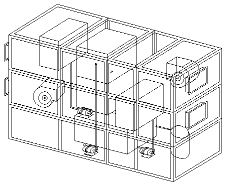
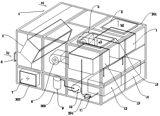
[0026] Such as figure 2 As shown, the structure of a solution humidity control fresh air unit includes a casing 201 formed with an air inlet and an air outlet. The casing 201 includes a heat recovery section 202, a fan section 203, and a solution section 204. Each section is divided into The upper and lower parts, the upper and lower parts are not connected to each other, the upper part of each section is connected to form an air circulation channel, the upper part of the fan section 203 and the solution section 204 is divided into two parts, the left and right parts are not connected to each other , forming two independent air passages on the left and right; the heat recovery section 202 is divided into two independent air passages by the plate heat recovery device 5, which are respectively connected with the left and right air passages, forming a side of the casing 201 from the unit Two independent air passages to the other side are fresh air passages and exhaust air passag...


PUM


Abstract

The invention discloses a structure of a solution humidity adjusting fresh air unit comprises a machine shell, and an air suction opening and an exhaust opening are formed in the machine shell; the machine shell comprises a heat recycling segment, a fan segment and a solution segment, and each segment is divided into an upper portion and a lower portion which cannot be communicated; the upper portions are connected to form an air circulation channel, and the upper portion of the fan segment and the upper portion of the solution segment are two left and right independent air channels which are not communicated; the heat recycling segment is divided by a plate type heat reclaiming device into two independent air channels which are connected with the left and right air channels, and a fresh air channel and an air exhaust channel which are independent and penetrate from one side of the machine shell to the other side are formed; the fresh air channel and the air exhaust channel on the lower portion and the upper portion of the machine shell are isolated, and refrigeration dehumidifying is utilized for pre-dehumidified fresh air; then, liquid dehumidifying is utilized for further dehumidifying the pre-dehumidified fresh air; and the structure of the solution humidity adjusting fresh air unit is designed and is simple in structure, convenient to manufacture and mount, flexible, and high in comprehensive energy efficiency.

Description

technical field [0001] The invention relates to a humidity-regulating air-conditioning unit, in particular to the structure of a solution-humidity-regulating fresh air unit which uses a solution to dehumidify or adjust humidity. The invention belongs to the field of heating, ventilating and air-conditioning. Background technique [0002] In the HVAC industry and engineering use, the commonly used dehumidification methods and systems can be roughly divided into cooling dehumidification and chemical dehumidification, which are represented by freezing dehumidification and solution dehumidification. The two are the most widely used methods. The main technical solution of the solution dehumidification method is to use a salt solution with hygroscopic properties as the working medium, and directly contact with the fresh air for heat and mass transfer to realize the dehumidification process of the fresh air. Due to its lower energy consumption and stronger dehumidification capacity...

Claims


Application Information

Patent Timeline
Patent Type & Authority Patents(China)
IPC IPC(8): F24F3/147F24F3/14
CPCF24F3/14F24F3/147F24F2003/144Y02P80/15
Inventor 姚永明倪庆海
Owner 江苏高科应用科学研究所有限公司
Why Eureka
Try Eureka