Multifunctional projection device

A projection device and multi-functional technology, applied in projection devices, projectors with built-in screens/external screens, optics, etc., can solve problems such as single projection mode, and achieve the effect of easy use and adjustment of projection angles

Active Publication Date: 2015-09-09
QINGDAO GOERTEK
View PDF6 Cites 3 Cited by
  • Summary
  • Abstract
  • Description
  • Claims
  • Application Information

AI Technical Summary

Problems solved by technology

[0003] The technical problem to be solved by the embodiments of the present invention is to provide a multi-functional projection device, which aims to solve the problem of single p

Method used


Image

  • Multifunctional projection device
  • Multifunctional projection device
  • Multifunctional projection device

Examples


Example

[0024] First embodiment

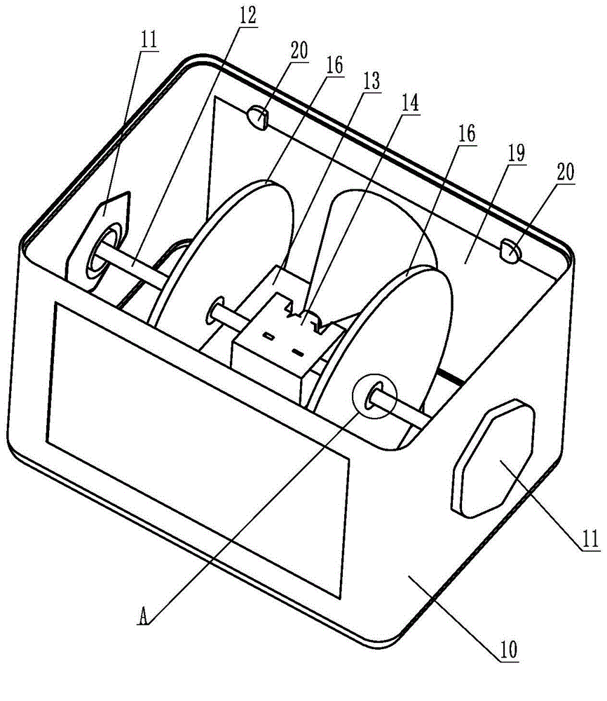
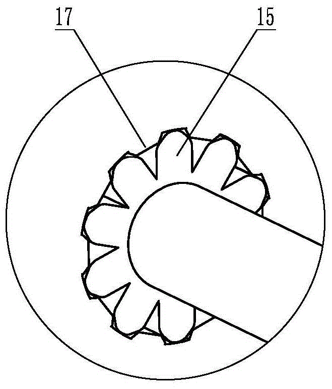
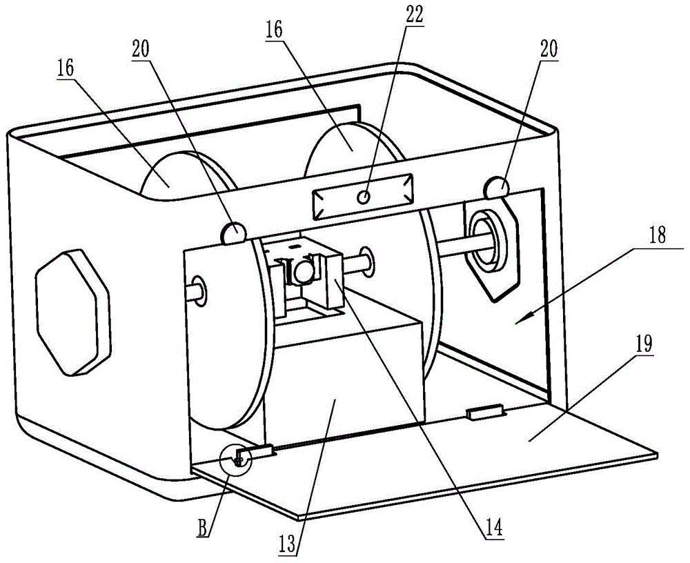
[0025] Figure 1 to Figure 5 It is a schematic diagram of the structure of a multifunctional projection device according to an embodiment of the present invention, in which, figure 1 Shows a schematic diagram (1) of the three-dimensional structure of the multifunctional projection device of the present invention, figure 2 show figure 1 Schematic diagram of enlarged structure at middle A, image 3 Shows a schematic diagram (2) of the three-dimensional structure of the multifunctional projection device of the present invention, Figure 4 show image 3 Schematic diagram of enlarged structure at middle B, Figure 5 The schematic diagram of the structure of the rotary switch is shown. For ease of expression, only the parts related to the present invention are shown in the figure.

[0026] by Figure 1 to Figure 5 It can be seen that the multifunctional projection device includes a housing 10, two opposite outer side walls of the housing 10 are respectively pro...

Example

[0033] Second embodiment

[0034] by Image 6 It can be seen that this embodiment is basically the same as the first embodiment. The difference is that the positioning member 16 is provided on one side of the transmission shaft 12, and the positioning member 16 is provided on the side close to the transmission shaft 12 with the transmission shaft. A number of positioning gear teeth 23 meshed with gear 15. The effect of adjusting the projection angle of the projector 14 can also be achieved.

Example

[0035] The third embodiment

[0036] This embodiment is basically the same as the first embodiment. The difference is that there are two transmission shafts 12, which are symmetrically arranged between the projector 14 and the horn 11 on the adjacent side.


PUM


Abstract

The invention belongs to the technical field of electronic products, and especially relates to a multifunctional projection device. The device comprises a projection light machine and a housing. An outer side wall of the housing is provided with a loudspeaker which is rotatingly connected with the outer side wall of the housing and electrically connected with the projection light machine. The interior of a cavity formed by the enclosing of the housing is provided with a transmission shaft which is fixedly connected with the loudspeaker and the projection light machine. An adjustment device which is used for adjusting a projection angle is disposed between the transmission shaft and the housing. A side wall, opposite to a lens of the projection light machine, of the housing is provided with a window, and the window is provided with a detachable projection screen. When the device is in use, an image can be projected on the projection screen, and also the projection screen can be opened to enable the image to be projected on a wall, thereby solving a problem that the number of projection mode is very small. The device can provide different projection modes according to the different needs of a user. In use, the loudspeaker can be rotated to drive the projection light machine fixedly connected with the transmission shaft to rotate, thereby achieving the purpose of adjusting the projection angle.

Description

Technical field [0001] The invention belongs to the technical field of electronic products, and in particular relates to a multifunctional projection device. Background technique [0002] With the advancement of society and the development of technology, more and more parent-child smart toys have entered people’s daily lives. Smart toys are equipped with projection devices. Parents can use remote Internet technology to remotely control, play and project videos. On the wall, the projection device of the existing parent-child smart toy is fixed inside the toy without a corresponding position adjustment mechanism. The position of the projection area can only be adjusted by moving the entire product during projection, and the single projection mode cannot meet the demand. Summary of the invention [0003] The technical problem to be solved by the embodiments of the present invention is to provide a multifunctional projection device, which aims to solve the problem of a single projecti...

Claims


Application Information

Patent Timeline
IPC IPC(8): G03B21/14G03B21/10G03B31/00
CPCG03B21/10G03B21/14G03B31/00
Inventor 侯飞冯涛
Owner QINGDAO GOERTEK
Why Eureka
Try Eureka