Power cable connecting terminal combined member

A technology for connecting terminals and power cables, which is applied in the field of power cable connection terminal assemblies, can solve problems affecting power supply reliability, production and life, and cumbersome procedures, and achieve safe and fast assembly mobility, high social and economic benefits, and high operating technology simple effect

Active Publication Date: 2015-09-09
STATE GRID CORP OF CHINA +2
View PDF9 Cites 0 Cited by
  • Summary
  • Abstract
  • Description
  • Claims
  • Application Information

AI Technical Summary

Problems solved by technology

[0002] In the past, the connecting conductors of the domestic cable connecting terminals were all bare type, which were easy to discharge, short circuit, electric shock, and many potential safety hazards. The cable connecting members of the European-style cable branch box were equipped with insulating jackets to prevent discharge, short circuit, and electric shock. The metal conductor and its external insulator are separate parts, so when the connecting terminal is connected to the wall bushing or the live connection member of the electrical equipment, the internal conductor and the external insulator need to be connected one by one, the process is cumbersome, and the operation flexibility is not strong and time-consuming Longer; and the operation process cannot be carried out with electricity, which will affect the reliability of power supply, have a great impact on production and life, and cause economic losses

Method used


Image

  • Power cable connecting terminal combined member
  • Power cable connecting terminal combined member
  • Power cable connecting terminal combined member

Examples


Embodiment 1

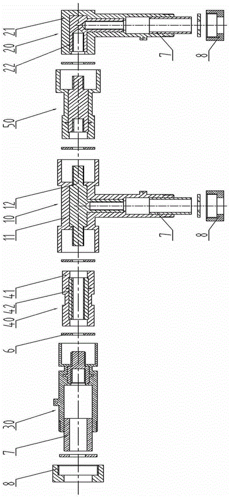
[0021] Preferred embodiment one, such as figure 1 As shown, this embodiment discloses a power cable connection terminal assembly, including a type I T-type connection terminal 10, a type I L-type connection terminal 20, a type I linear connection terminal 30, a type I butt joint 40, a type II Butt joint 50, rubber pad 6. Type I T-shaped connecting terminal 10, Type I L-shaped connecting terminal 20, Type I straight connecting terminal 30, Type I butt joint 40 and Type II butt joint 50 are all integral parts of inner conductor and outer hard insulating sleeve. The conductor insulation is enclosed in a hard insulating sleeve, and the connection ends of the internal conductors are all threaded.

[0022] Type I T-shaped connecting terminal 10 includes a T-shaped hard insulating sleeve 11 and a T-shaped inner conductor 12 embedded in its axial center. Threaded connection hole, the length of the three directions of the T-shaped hard insulating sleeve 11 is greater than the corresp...

Embodiment 2

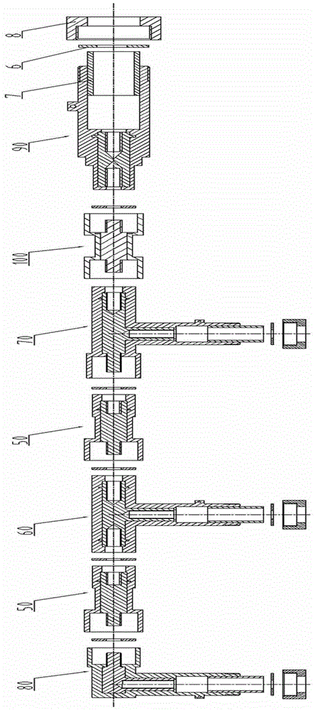
[0032] Preferred embodiment 2. The difference between this embodiment and preferred embodiment 1 is that this embodiment includes a Type II T-shaped connecting terminal 60 and a Type III T-shaped connecting terminal 70, a Type II L-shaped connecting terminal 80 and a Type II T-shaped connecting terminal. One straight connecting terminal 90 , two type II butt joints 50 and one type III butt joint 100 . The connection structure of the two connection ends of the T-shaped internal conductor head of the type II T-shaped connection terminal 60 is an internal thread hole, and the connection structure of the two connection ends of the T-shaped internal conductor head of the type III T-shaped connection terminal 70 is an external thread head, Internally threaded hole at the other end; Type II L-type connecting terminal 80 internal connecting conductor horizontal connection end is an external thread head; Type II straight connecting terminal 90 internally connecting conductor both ends a...


PUM


Abstract

The invention discloses a power cable connecting terminal combined member which comprises a T-shaped connecting terminal, an L-shaped connecting terminal, a linear connecting terminal and a docking joint. Any two or three of the T-shaped connecting terminal, the L-shaped connecting terminal and the linear connecting terminal are connected into a whole through the docking joint, each of the T-shaped connecting terminal, the L-shaped connecting terminal, the linear connecting terminal and the docking joint is an integral member composed of an inside conductor and an outside hard insulating sleeve, each inside conductor is sealed in the corresponding hard insulating sleeve in an insulated manner, and a connecting end of each inside conductor is of a threaded connecting structure. A user only contacts with the outside insulating sleeves during operation, so that electrified connection can be realized. Each of the T-shaped connecting terminal, the L-shaped connecting terminal, the linear connecting terminal and the docking joint has various structures, combining of the terminals is flexible, the terminals can be connected to form the combined member having different structures according to needs, and the power cable connecting terminal combined member is wide in application range.

Description

technical field [0001] The invention relates to a power cable connection terminal, in particular to a power cable connection terminal assembly formed by live connection of a plurality of cable connection terminals. Background technique [0002] In the past, the connecting conductors of the domestic cable connecting terminals were all exposed type, which were easy to discharge, short circuit, electric shock, and many potential safety hazards. The cable connecting members of the European-style cable branch box were equipped with insulating jackets to prevent discharge, short circuit, and electric shock. The metal conductor and its external insulator are separate parts, so when the connection terminal is connected to the wall bushing or the live connection member of the electrical equipment, the connection between the internal conductor and the external insulator needs to be carried out one by one, the process is cumbersome, and the operation flexibility is not strong and time-c...

Claims


Application Information

Patent Timeline
Patent Type & Authority Applications(China)
IPC IPC(8): H01R11/11H01R13/52H01R13/53
Inventor 邓晓廉戴兴周卫星方宇辉谭斌唐炅刘军志
Owner STATE GRID CORP OF CHINA
Why Eureka
Try Eureka