Front-piercing cable connection device

A technology for connecting devices and cables, applied in the parts, connections, coupling devices and other directions of connecting devices, can solve the problems of a large number of garbage and harmful gases, high personnel requirements, low construction efficiency, etc. Low requirements and good waterproof performance

Pending Publication Date: 2020-01-14
邢建峰
View PDF0 Cites 0 Cited by
  • Summary
  • Abstract
  • Description
  • Claims
  • Application Information

AI Technical Summary

Problems solved by technology

During the operation, the technical requirements for the construction personnel are high, a little carelessness will cause injury to the personnel, a large amount of garbage will be generated during the on-site construction, the reliability of the construction results is poor, the construction efficiency is low, and the occurrence rate of poor connection and poor waterproofness is high; cold pressing The auxiliary materials to be used for the terminal type are cold-pressed terminals, and the tools used include wire cutters, wire strippers or electrician's knives, cold-pressed pliers, screwdrivers, etc.
During operation, the construction personnel should be proficient in using various tools. A large amount of garbage will be generated during on-site construction. The reliability of the construction results is poor, the construction efficiency is low, and the incidence of poor connection and looseness is high. The auxiliary materials used for welding connection are solder and flux. etc. The tools used include wire cutters, wire strippers or electrician's knife, welding tools, and sometimes heat shrinkable tubes, blowtorches and other tools
This connection method is very complicated to operate and requires high personnel. During on-site construction, a large amount of garbage and harmful gases are generated, which is easy to cause injury to personnel, and the construction efficiency is very low.

Method used


Image

  • Front-piercing cable connection device
  • Front-piercing cable connection device
  • Front-piercing cable connection device

Examples


specific Embodiment 1

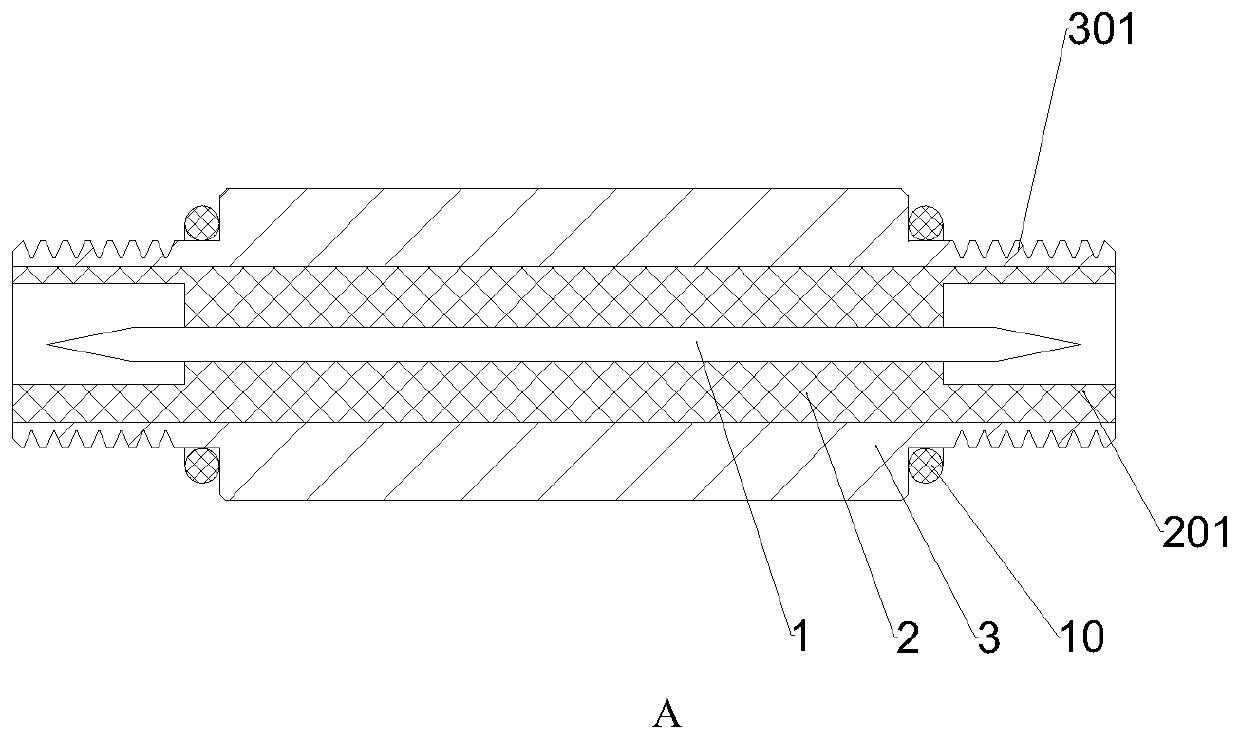
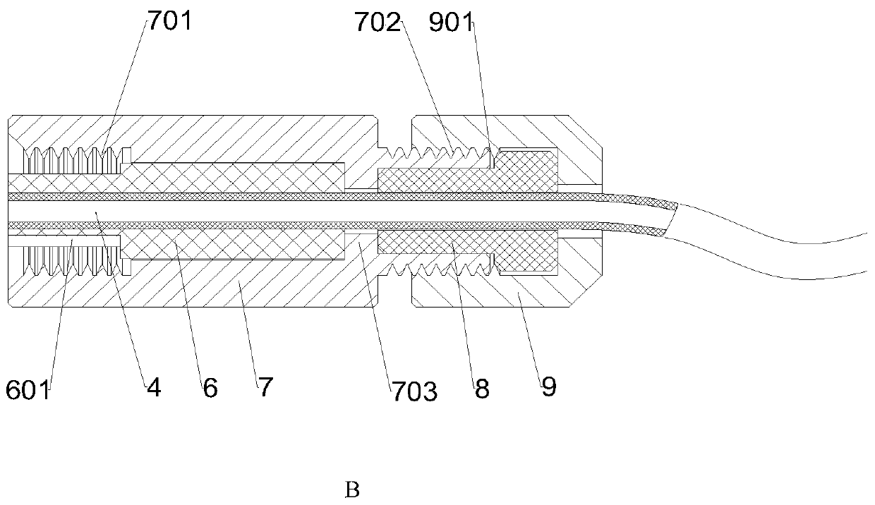
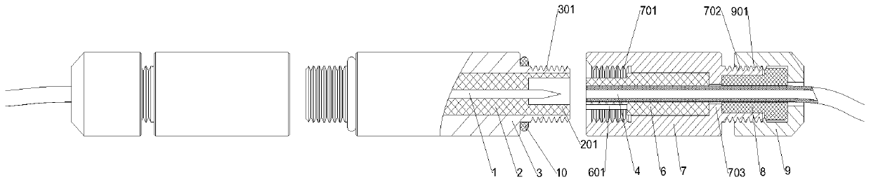
[0026] Specific embodiment 1, a front piercing type cable connection device, which includes an A component and a B component, and the A component includes a stabbing member 1, a stabbing member base 2, a first connection shell 3 and a second sealing member 10; Component B includes a second connection shell 7 , a cable positioning member 6 , a wire core 4 , a first sealing member 8 and a locking member 9 .

[0027] according to figure 1 and figure 2 Schematic diagram of the structure, component A is a cylindrical structure with a circular axial section. The piercing piece base 2 is provided with piercing piece 1 along its length direction; the inner walls of both ends of the piercing piece base 2 are provided with protrusions 201; the piercing piece 1 penetrates and is fixedly connected to the piercing piece base 2; the piercing piece The base body 2 is fixed in the first connection shell 3; the extensions at both ends of the first connection shell 3 are provided with extern...


PUM


Abstract

The invention discloses a front-piercing cable connection device, including a device body. The device body includes an A component and a B component. The A component includes a piercing member, a piercing member base, a first connection housing and second sealing members. The B component includes a second connection housing, a cable positioning member, a wire core, a first sealing member, and a locking member. The piercing member penetrates through the piercing member base along the length direction of the piercing member base. Both ends of the piercing member base are provided with protrusions. The outer side of the piercing member base is fixedly connected with the first connection housing and is provided with external threads. Both ends of the external threads are sleeved with the second sealing members. The cable positioning member is sleeved therein with the wire core, and is sleeved with the second connection housing at its outer wall end. A groove is disposed outside the upper end of the cable positioning member. The first sealing member sleeves the end portion of the second connection housing. The locking member is disposed on the end portion of the first sealing member. The front-piercing cable connection device is easy to operate and reliable in connection, causes no harm to users, generates no harmful gas, and requires no heating tool.

Description

technical field [0001] The invention relates to a cable connection device, in particular to a front-piercing type cable connection device. Background technique [0002] The existing cable connection methods include: twisted type, cold-pressed terminal type, welding type and so on. [0003] The existing connection methods all need to strip the core sheath, and the auxiliary material required by the splicing type is waterproof tape, and the tools used include wire cutters, wire strippers or electrician's knives. During the operation, the technical requirements for the construction personnel are high, a little carelessness will cause injury to the personnel, a large amount of garbage will be generated during on-site construction, the reliability of the construction results is poor, the construction efficiency is low, and the occurrence rate of poor connection and poor waterproofness is high; cold pressing The auxiliary materials to be used for the terminal type are cold-presse...

Claims


Application Information

Patent Timeline
Patent Type & Authority Applications(China)
IPC IPC(8): H01R11/09H01R11/20H01R13/52H01R13/623
CPCH01R11/09H01R11/20H01R13/5205H01R13/623
Inventor 邢建峰
Owner 邢建峰
Why Eureka
Try Eureka