Motor, Motor device and pointer type display device
A motor and rotor technology, applied in the field of pointer display devices, can solve the problems of reduced bearing life, rotor vibration, etc.
- Summary
- Abstract
- Description
- Claims
- Application Information
AI Technical Summary
Problems solved by technology
Method used
Image
Examples
Embodiment approach 1
[0052] (The overall structure of the motor unit)
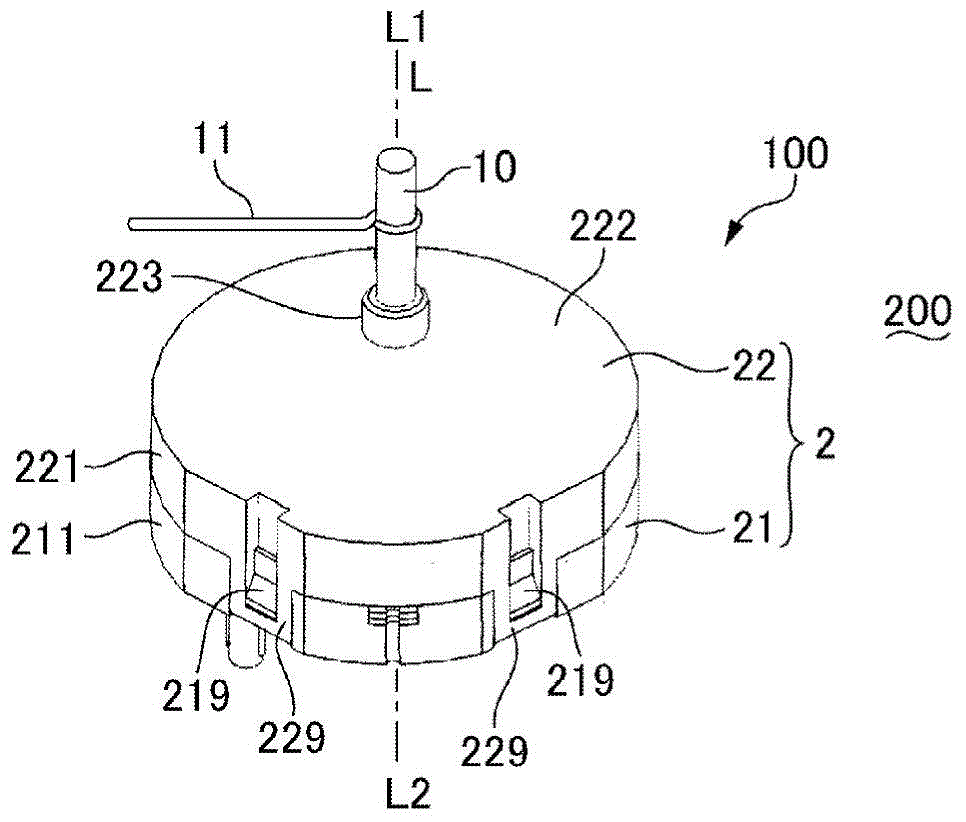
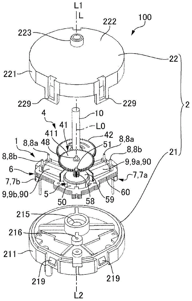
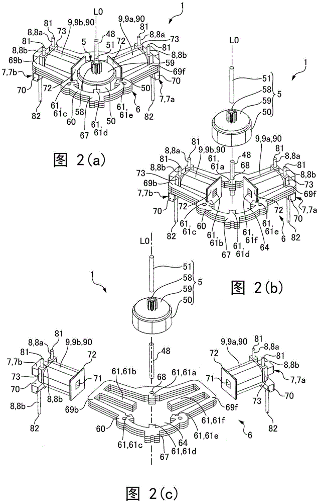
[0053] 1( a ) and FIG. 1( b ) are explanatory diagrams of the motor device 100 according to Embodiment 1 of the present invention, and FIG. 1( a ) is a view of the motor device 100 viewed from the side where the output shaft 10 protrudes. Perspective view, FIG. 1( b ) is an exploded view of the motor device 100 viewed from the side where the output shaft 10 protrudes. In the following description, the protruding side of the output shaft 10 in the direction in which the axis L of the output shaft 10 extends is defined as one side L1 , and the side opposite to the protruding side of the output shaft 10 is defined as the other side L2 . Also, let the axis of the rotor 5 of the motor 1 be the rotation center axis L0. In addition, for convenience, one side of the rotation center axis L0 is also referred to as one side L1, and the other side of the rotation center axis L0 is also described as the other side L2.
[0054] The motor ...
Embodiment approach 2
[0095] Figure 6 It is an explanatory diagram schematically showing the air gap between the salient pole 61 of the motor 1 and the magnet 50 used in the motor device 100 according to Embodiment 2 of the present invention. 7(a) and 7(b) are explanatory views of the stator core 60 used in the motor 1 of the motor device 100 according to Embodiment 2 of the present invention, and FIG. 7(a) is a perspective view of the stator core 60. , FIG. 7(b) is an exploded view of the stator core 60. In addition, since the basic structure of this embodiment is the same as Embodiment 1, the same code|symbol is attached|subjected to the same part, and the description is abbreviate|omitted.
[0096] Such as Figure 6 As shown, the present embodiment is the same as Embodiment 1, and the structure of the air gap sandwiched between the end portions 610f, 610b of the main poles (salient poles 61f, 61b) and the outer peripheral surface of the magnet 50 is similar to that of the first auxiliary pole...
Embodiment approach 3
[0116] Figure 10 It is an explanatory diagram schematically showing the air gap between the salient pole 61 of the motor 1 and the magnet 50 used in the motor device 100 according to Embodiment 3 of the present invention. In addition, since the basic structure of this embodiment is the same as that of the embodiment, the same code|symbol is attached|subjected to the same part, and the description is abbreviate|omitted.
[0117] Such as Figure 10 As shown, in the present embodiment, S poles and N poles are alternately formed on the outer peripheral surface of the magnet 50 at equal angular intervals. In the present embodiment, five pairs of S poles and N poles are formed in the magnet 50 . Therefore, in the magnet 50, a total of ten N poles and S poles are formed at equal angular intervals, so that the angular positions of the adjacent S poles and N poles in the circumferential direction are shifted by 36°.
[0118] In the stator core 60 , three salient poles 61 are formed...
PUM
 Abstract
Description
Claims
Application Information
 - R&D
- Intellectual Property
- Life Sciences
- Materials
- Tech Scout
- Unparalleled Data Quality
- Higher Quality Content
- 60% Fewer Hallucinations
Browse by: Latest US Patents, China's latest patents, Technical Efficacy Thesaurus, Application Domain, Technology Topic, Popular Technical Reports.
© 2025 PatSnap. All rights reserved.Legal|Privacy policy|Modern Slavery Act Transparency Statement|Sitemap|About US| Contact US: help@patsnap.com


