Integrated wavefront sensor and profilometer

一种波前传感器、轮廓测定仪的技术,应用在光学仪器测试、机器/结构部件的测试、仪器等方向,能够解决耗时、难以实现精度等问题

Active Publication Date: 2015-09-09
QED TECH INT
View PDF11 Cites 2 Cited by
  • Summary
  • Abstract
  • Description
  • Claims
  • Application Information

AI Technical Summary

Problems solved by technology

Measurement of multiple axes is difficult to achieve the required accuracy and measurement of a large number of individual points covering the test surface with sufficient resolution is time consuming

Method used


Image

  • Integrated wavefront sensor and profilometer
  • Integrated wavefront sensor and profilometer
  • Integrated wavefront sensor and profilometer

Examples


Embodiment Construction

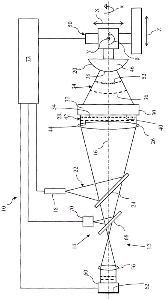
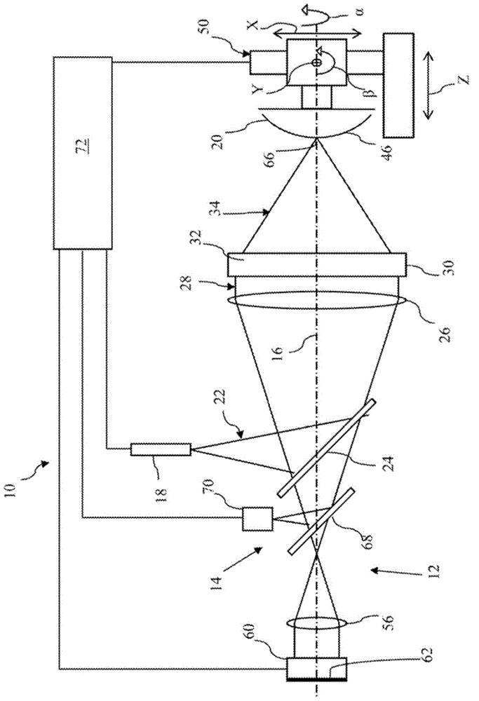
[0031] pass figure 1 and figure 2 An embodiment of the invention is depicted as an integrated optical wavefront sensor and single point profilometer 10 in two different operating settings. exist figure 1 In , the integrated optical wavefront sensor and single-point profilometer 10 is arranged as an optical wavefront sensor 12 for measurement. exist figure 2 In , the integrated optical wavefront sensor and single-point profilometer 10 is arranged as a single-point profilometer 14 for measurement. Optical wavefront sensor 12 and single point profilometer 10 share a common axis 16 and a plurality of optics arranged along optical axis 16 for delivering light from a common light source 18 to aspheric test surface 20 .

[0032] The common light source 18 emits a diverging measurement beam 22 which is reflected by a beam splitter 24 to propagate along the optical axis 16 . As with conventional optical wavefront sensors and single point profilometers, light source 18 may be any...


PUM


Abstract

An instrument for measuring aspheric optical surfaces includes both an optical wavefront sensor and a single-point optical profilometer. The optical wavefront sensor measures surface height variations throughout one or more areas of an aspheric test surface. The single-point profilometer measures surface height variations along one or more traces on the aspheric test surface. At least one of the traces intersects at least one of the areas, and respective spatial frames of reference for the traces and areas are relatively adapted to each other by minimizing differences between points of nominal coincidence between the areas and traces.

Description

technical field [0001] The present invention relates to the measurement of aspheric surfaces using a combination of optical measurement techniques in the field of optical metrology, and thus, in particular to both optical wavefront sensing and single-point profilometry, and the integration of measurements by such techniques . Background technique [0002] Measuring aspheric surfaces, which can generally be defined as surfaces distinct from planar, cylindrical, and spherical surfaces, presents many challenges compared to surfaces of simpler form. Despite the added difficulty of measuring them, aspheric surfaces must often be measured with a precision similar to that of simpler forms of surfaces. A particular problem with measuring aspheric surfaces is the large variation in local curvature and slope of the aspheric surface, which can be difficult to capture and compare to a datum. [0003] In conventional surface measurement techniques, optical wavefront sensing typically p...

Claims


Application Information

Patent Timeline
Patent Type & Authority Applications(China)
IPC IPC(8): G01B11/24G01M11/00
CPCG01M11/025G01M11/005G01M11/0271
Inventor A.库拉威克P.墨菲J.弗莱格
Owner QED TECH INT
Why Eureka
Try Eureka