Signal-to-noise ratio tuned adaptive optics control system

Inactive Publication Date: 2005-01-13
THE BOEING CO
View PDF3 Cites 52 Cited by
  • Summary
  • Abstract
  • Description
  • Claims
  • Application Information

AI Technical Summary

Benefits of technology

FIG. 5 is a diagram of the signal processing o

Problems solved by technology

Optical wavefronts are subject to distortion when passed through certain mediums.
These distortions can degrade the quality of images of an object being observed through an image-forming device such as a camera or telescope.
Such distortions and degradations can be especially severe and problematic in turbulent mediums such as the atmosphere.
This method, however, only provides a small improvement in the sharpness of the image in applications involving large telescopes.
Current wavefront slope sensors, however, are subject to various measurement errors that degrade wavefront correction.
First, there is noise in each measurement, including read-out noise and dark-current noise in the detector and shot noise in the received light.
Second, diffractive cross-talk can be produced among adjacent subapertures.
Third, the subapertures and detectors may be misaligned.
Fourth, partially filled lenslets can cause stretching of the spot size on the detectors.
Fifth, the intensity across each lenslet may not be uniform, which can also change the spot sizes and shapes.
In addition, Hartmann wavefront sensors are unable to provide accurate wavefront phase slope m

Method used


Image

  • Signal-to-noise ratio tuned adaptive optics control system
  • Signal-to-noise ratio tuned adaptive optics control system
  • Signal-to-noise ratio tuned adaptive optics control system

Examples


Embodiment Construction

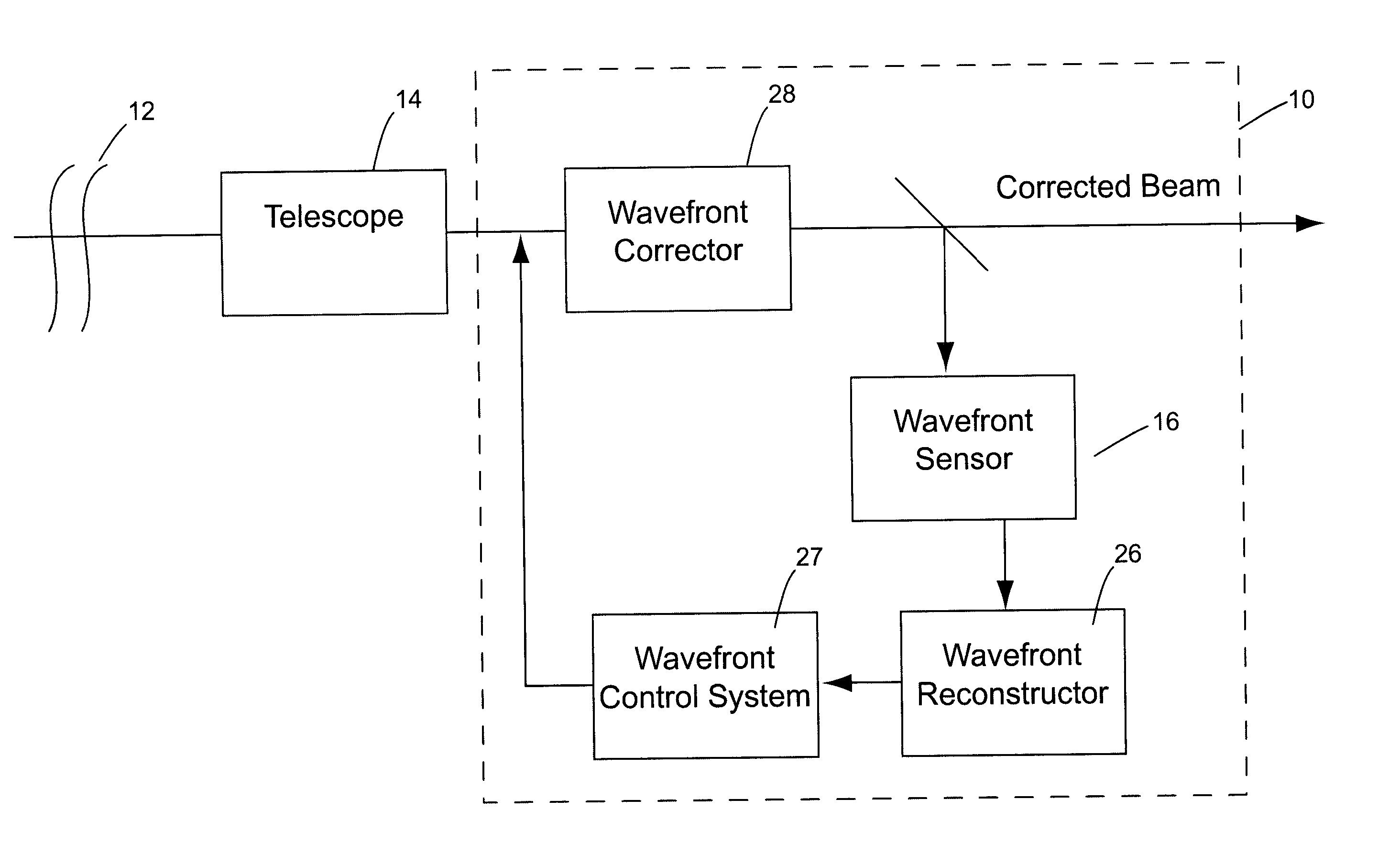
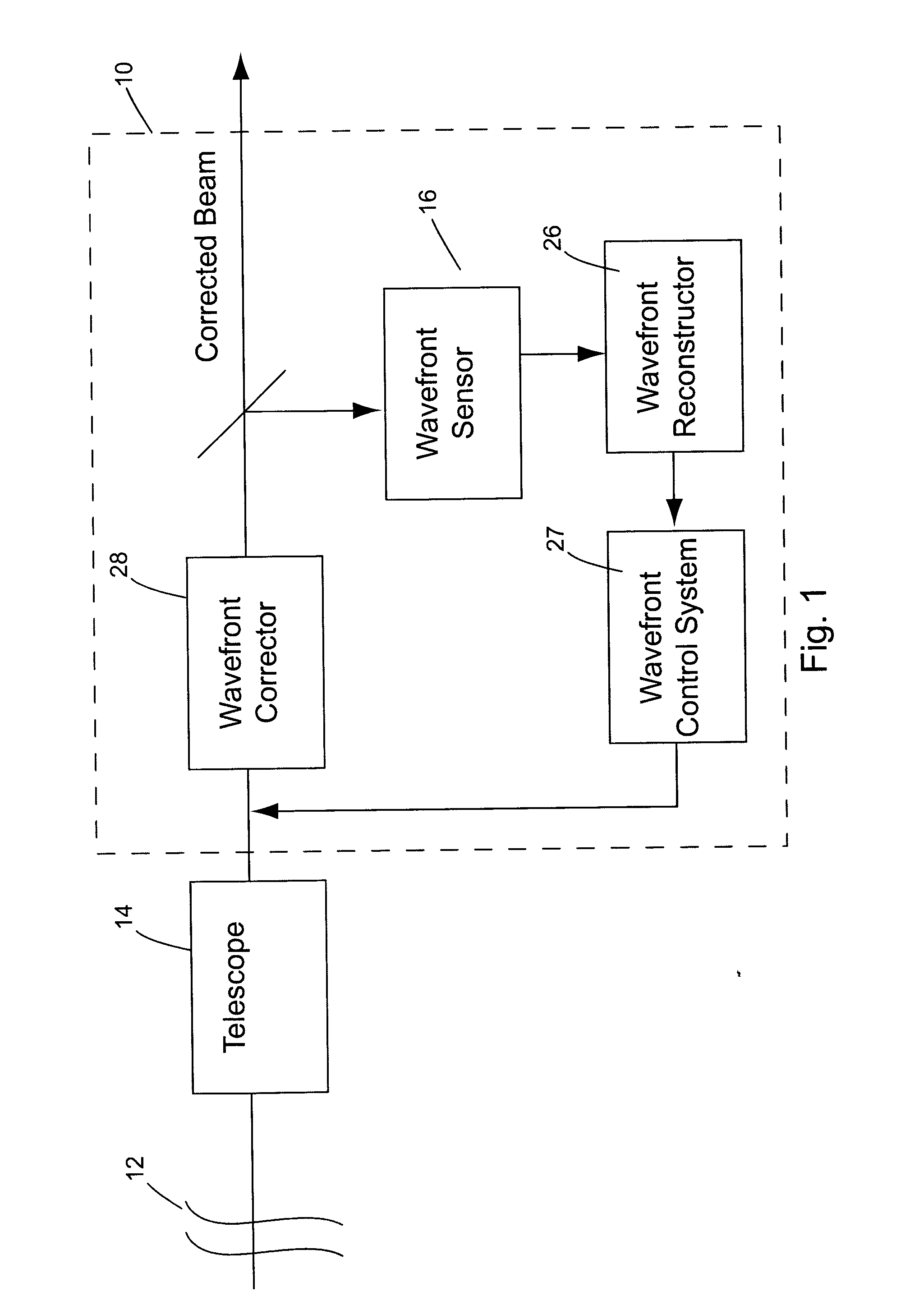
An adaptive optics control system 10 for correcting distortions in a wavefront 12 in accordance with one embodiment of the present invention is shown in FIG. 1. While the system will be discussed in connection with a telescope 14 for space observations, it can be appreciated that it can be used with any device and in connection with any medium involving optical wavefronts which are subject to distortion. The system 10 is a closed loop system consisting generally of a wavefront slope sensor 16, a wavefront reconstructor 26, a wavefront control system 27 and a wavefront corrector 28.

While the wavefront corrector will be discussed in connection with a deformable mirror, it can be appreciated that any spatial light modulator may be used and the term deformable mirror as used herein applies to both. As shown in FIG. 4, the deformable mirror 28 comprises a thin reflective surface 30 controlled by a plurality of actuators 32 secured to the back thereof. In a preferred embodiment, the ac...


PUM


Abstract

An improved, adaptive optics control system having a signal-to-noise ratio-tuned wavefront corrector is disclosed. The system comprises a wavefront corrector, a wavefront sensor, a wavefront reconstructor and a wavefront controller. The wavefront corrector has a surface controlled by a plurality of actuators. The wavefront slope sensor has a subaperture separation mechanism for defining a plurality of subapertures through which the distorted wavefront can pass, each subaperture corresponding to an actuator of the wavefront corrector. The wavefront slope sensor produces a wavefront sensor output signal for each subaperture indicative of the distortion of the wavefront. The wavefront reconstructor is adapted to receive the wavefront sensor output signals and calculate corresponding phase estimates based thereon, each phase estimate having a signal-to-noise ratio. The wavefront reconstructor generates a plurality of correction signals to be applied to each of the actuators of the wavefront corrector, each correction signal having a bandwidth. The wavefront controller is adapted to selectively adjust the bandwidth of each correction signal based on the signal-to-noise ratio of the corresponding phase estimate of the actuator to which it is to be applied. A method of optical wavefront distortion correction is also disclosed.

Description

CROSS REFERENCE TO RELATED APPLICATIONS None. STATEMENT REGARDING FEDERALLY SPONSORED RESEARCH OR DEVELOPMENT None. BACKGROUND OF INVENTION The present invention relates to an improved adaptive optics control system and in particular, to a signal-to-noise ratio-tuned wavefront corrector for use therein. Optical wavefronts are subject to distortion when passed through certain mediums. These distortions can degrade the quality of images of an object being observed through an image-forming device such as a camera or telescope. Such distortions and degradations can be especially severe and problematic in turbulent mediums such as the atmosphere. Some of the diffractive effects of such turbulence include image blurring caused by the turbulence aberrations, scintillation caused by propagation through strong turbulence, and speckle caused by coherent scattering from diffuse objects. Various adaptive optic control systems, mechanisms and methods have been developed to try to correct fo...

Claims


Application Information

Patent Timeline
IPC IPC(8): G01J9/00G02B26/06
CPCG01J1/4257G02B26/06G01J9/00
Inventor SMITH, CAREY A.
Owner THE BOEING CO
Why Eureka
Try Eureka