Systems and methods of phase diversity wavefront sensing

a wavefront sensor and phase diversity technology, applied in the field of wavefront measurement, can solve the problems of affecting the measurement accuracy of optical elements produced by multifocal optical elements, and affecting the measurement accuracy of optical elements

Active Publication Date: 2009-07-23
AMO DEVMENT
View PDF11 Cites 53 Cited by
  • Summary
  • Abstract
  • Description
  • Claims
  • Application Information

AI Technical Summary

Problems solved by technology

However, a SHWS has some limitations in certain applications.
In general, an SHWS has difficulty measuring wavefronts with discontinuities.
However, in some applications, and particularly in some ophthalmic applications, the wavefront may have multiple tilts, which may produce multiple focal spots.
So, it is difficult at best for a SHWS to measure wavefronts produced by multifocal optical elements, such as diffractive IOLs.
Another limitation of the SHWS pertains to its limited dynamic range.
This can add to the complexity and cost of the measurement system, and requires alignment that can reduce the measurement precision of the instrument.
Early PDWS systems employed a relatively complex arrangement of beam splitters and / or optical delays to generate the necessary images.
However, the procedure described therein is not extensible to more complicated configurations.
Nevertheless, these references are not generally directed to applications where there is speckle and / or discontinuities or large aberrations in the wavefront, such as may be the case in many ophthalmic applications, including the measurement of IOLs, multifocal contact lenses, etc., and eyes or optical systems that include such devices.
Furthermore, these references do not provide a generalized design method for incorporating a PDWS into more complicated optical systems.

Method used


Image

  • Systems and methods of phase diversity wavefront sensing
  • Systems and methods of phase diversity wavefront sensing
  • Systems and methods of phase diversity wavefront sensing

Examples


Embodiment Construction

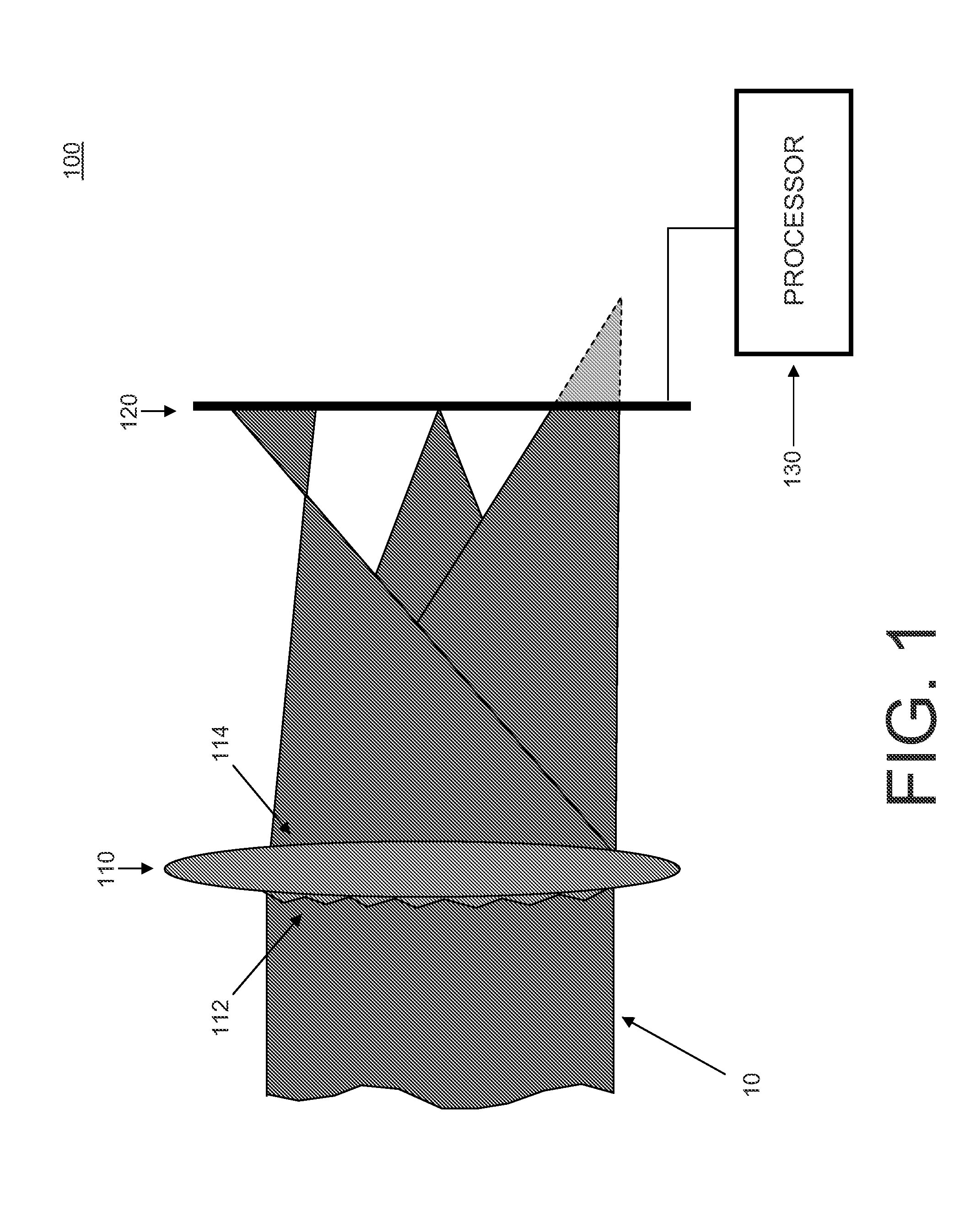
[0039]FIG. 1 illustrates the use of a diffractive optical element (DOE) in a phase diversity wavefront sensor (PDWS) 100. PDWS 100 includes an optical element 110, a detector 120, and a processor 130. Optical element 110 includes a diffractive optical element (DOE) (e.g., a diffraction grating) 112 collocated with optical element 114 with positive focal power. Although shown in transmission mode, optical element 110 may alternately be used in reflection where diffraction grating 114 is collocated with optical element 114 comprising a mirror.

[0040]In the illustrated embodiment, optical element 114 is a lens, and diffractive grating 112 is disposed on a surface of lens 114. Alternatively, diffractive grating 112 may be incorporated inside lens 114 or be formed from the material used to form lens 114. In some embodiments, lens 114 and diffractive grating 112 form a single DOE, where lens 114 is itself a DOE, for example, disposed on a same surface or an opposite surface as diffractive ...


PUM


Abstract

A phase diversity wavefront sensor includes an optical system including at least one optical element for receiving a light beam; a diffractive optical element having a diffractive pattern defining a filter function, the diffractive optical element being arranged to produce, in conjunction with the optical system, images from the light beam associated with at least two diffraction orders; and a detector for detecting the images and outputting image data corresponding to the detected images. In one embodiment, the optical system, diffractive optical element, and detector are arranged to provide telecentric, pupil plane images of the light beam. A processor receives the image data from the detector, and executes a Gerchberg-Saxton phase retrieval algorithm to measure the wavefront of the light beam.

Description

CROSS-REFERENCES TO RELATED APPLICATIONS[0001]This patent application claims the priority benefit under 35 U.S.C. § 119(e) from U.S. provisional patent application 60 / 983,380 filed on 30 Oct. 2007, U.S. provisional patent application 61 / 028,877 filed on 14 Feb. 2008, and U.S. provisional patent application 61 / 048,042 filed on 25 Apr. 2008, each filed in the names of Thomas D. Raymond et al., the entirety of each of which is hereby incorporated herein by reference for all purposes as if fully set forth herein.BACKGROUND AND SUMMARY[0002]1. Field[0003]This invention pertains to the field of wavefront measurements, and more particularly to systems and methods of measuring a wavefront of light using a phase diversity wavefront sensor.[0004]2. Description[0005]A number of systems and methods have been developed for measuring a wavefront of light. Such wavefront measurements have been employed in a number of applications, including ophthalmic applications such as measuring aberrations of ...

Claims


Application Information

Patent Timeline
Patent Type & Authority Applications(United States)
IPC IPC(8): A61B3/10G01B9/00G06F17/50G01M11/02
CPCA61B3/1015G01M11/0292G01J9/00
Inventor RAYMOND, THOMAS D.PULASKI, PAULFARRER, STEPHEN W.NEAL, DANIEL R.GREENAWAY, ALAN H.FAICHNIE, DAVID M.CAMPBELL DALGARNO, HEATHER I.CRAIK, GRAHAM N.
Owner AMO DEVMENT
Why Eureka
Try Eureka