Geometrically-desensitized interferometer incorporating an optical assembly with high stray-beam management capability

a technology of optical assembly and geometries, applied in the field of geometries, can solve the problems of low resolution, unsuitable for many applications in which surface profiles must be measured with high precision, and conventional psi approaches can only profile smooth surfaces having relatively small heights, so as to reduce the number of back reflections, reduce the effect of ghost imaging and high measurement accuracy

Inactive Publication Date: 2000-06-06
ZYGO CORPORATION
View PDF6 Cites 45 Cited by
  • Summary
  • Abstract
  • Description
  • Claims
  • Application Information

AI Technical Summary

Benefits of technology

It is therefore a principal object of the invention to provide a GDI instrument having an optical assembly that reduces the number of back re

Problems solved by technology

Geometric techniques are relatively insensitive to surface roughness and deformations, but are of relatively low resolution--so low, in fact, that they are unsuitable for many applications in which surface profiles must be measured with high precision.
This wavefront of coherent light is then reflected off test and reference surfaces to produce first and second reflected wavefronts which combine with one another while interfering both constructively and destructively to produce an interference fringe pattern.
Generally speaking, however, conventional PSI approaches can only profile smooth surfaces having relatively small height variations or "surface departures" between adjacent measurement sites.
Stated another way, the maximum phase difference between the reference and test light beams must have an absolute value which is less than .pi.. This constraint, sometimes known as "two .pi. ambiguity", arises because the arctangent function, which is used to convert phase to distance, is only unique within the range of .+-..pi.. Thus, although the use of phase measurements advantageously allows very high precision to be obtained, it disadvantageously limits the maximum surface departure between adjacent measurement sites to one quarter of the source's optical wavelength.
A further difficulty with PSI arises when the surface slope is so large that it becomes difficult to resolve or distinguish the interference fringes because the fringe density is too high.
Therefore, while PSI interferometry is much more precise than geometric optical profilometry, it historically has been considered to be ill-suited for use with rough objects or objects having marked surface deformations.
Interferometers using PSI analysis therefore historically have not been considered appropriate for some surface profilometry applications.
However, SWLI has disadvantages of its own that hinder its use in industrial applications.
When the field of view of the typical SWLI instrument is increased, the fringe density can easily become difficult to resolve even with very high resolution imaging devices.
This problem is especially evident during the profiling of rough surfaces.
The light loss means that larger surfaces require a more powerful illuminator.
Another disadvantage of typical SWLI techniques is that data acquisition is very slow.
Still another disadvantage of typical SWLI is its high sensitivity to vibration.
An instrument configured for SWLI analysis generally requires massive mounting fixtures and expensive vibration isolation.
Neither traditional PSI techniques nor traditional SWLI techniques are suitable for these purposes.
GDI instruments therefore can be us

Method used


Image

  • Geometrically-desensitized interferometer incorporating an optical assembly with high stray-beam management capability
  • Geometrically-desensitized interferometer incorporating an optical assembly with high stray-beam management capability
  • Geometrically-desensitized interferometer incorporating an optical assembly with high stray-beam management capability

Examples


second example

b. SECOND EXAMPLE

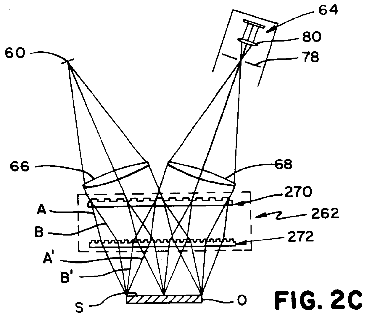
In some instances, it may be desirable to simplify the manufacturing process by constraining the substrates of both gratings 270 and 272 to be identical, i.e., to have identical maximum wedges and to have identical thickness. A member of the resultant family of optimal solutions is summarized in Table 2:

It should be appreciated from above that fewer parameters can be optimized due to the fact that the maximum wedge, wedge direction and substrate thickness must be the same for both of the diffraction gratings 270 and 272. As a result, while the average phase offset is zero, a tolerably small phase offset variation (on the order of .+-.6 fringes across a 100 mm field of view) remains across the instrument's field of view.

third example

c. THIRD EXAMPLE

In this example, further constraints were placed upon design versatility to further simplify manufacturing. The rotation of all surfaces of the substrates 270 and 272 about the X axis was constrained to be zero. This constraining requirement alone is sufficient to guarantee that the average phase offset is zero at the optimum metrology plane. Optimization of the five remaining tilt parameters (including that of the object O) can be used to steer stray beams away from the pupil 78 of the imaging device 64. Furthermore, if identical substrates are used for the two diffraction gratings 270 and 272, phase offset variations across the field of view are eliminated. A member of the resultant family of optimal solutions is tabulated in Table 3:

An instrument can be manufactured in accordance with this example even more easily than the prior examples because the wedges are oriented parallel to the substrate edge. Moreover, arranging the wedges of both diffractive surfaces in t...

fourth example

d. FOURTH EXAMPLE

This example follows a slightly different approach than the prior examples. In this approach, wedge and tilt are first optimized, without regard to phase offset, to maximize deviation of stray beams from the pupil 78. The average phase offset at the optimum metrology plane is then eliminated or at least minimized by suitable selection of the effective thickness of a portion of the optical assembly. For instance, and as seen in FIG. 6, the diffractive surface of the first grating 370 of an optical assembly 362 can be located on the bottom or rear surface of the grating's substrate as opposed to the front surface, thereby decreasing the effective thickness of that grating. Optical assembly 362 is otherwise identical to the optical assembly 262 of FIG. 2C, and its components therefore are denoted by the same reference numerals as the corresponding components of optical assembly 262, incremented by 100. A member of a family of solutions achieving the desired effects in ...


PUM


Abstract

The optical assembly of a GDI instrument is configured to deviate or steer stray beams away from the pupil of the instrument's imaging device and/or to suppress stray beams. Stray beam deviation is optimized by selecting particular wedge and/or tilt configurations that achieve the desired stray beam deviation while avoiding or at least minimizing phase offset at the optimum metrology plane. Stray beam suppression can be achieved by providing the diffractive groove profile of the instrument's optical assembly with smooth edges. The resultant profile facilitates effective diffraction order management as well as a reduction in back reflection. The invention is particularly well-suited for use with a GDI instrument in which the optical assembly comprises first and second diffraction gratings. In this case, any average phase offset that remains after setting wedge and/or tilt can be eliminated by inserting a suitable compensating plate between the first and second diffraction gratings or between the second diffraction grating and the object.

Description

1. Field of the InventionThe invention relates to interferometers and, more particularly, relates to a geometrically-desensitized interferometer (GDI) instrument for surface profiling. Even more particularly, the invention relates to a GDI instrument that includes an optical assembly configured to redirect and / or suppress stray beams. The invention additionally relates to a method of operating an interferometer with improved stray beam management capability.2. Discussion of the Related ArtOptical metrology of surface profiles can generally be divided into two regimes, namely interferometric and geometric. Geometric techniques include triangulation and moire fringe analysis, which involves the projection and imaging of a periodic structure such as a ronchi ruling. Geometric techniques are relatively insensitive to surface roughness and deformations, but are of relatively low resolution--so low, in fact, that they are unsuitable for many applications in which surface profiles must be ...

Claims


Application Information

Patent Timeline
IPC IPC(8): G01B11/24G01B11/30G01B9/02G02B5/18
CPCG01B11/306G01B11/2441
Inventor STEPHENSON, DAVIDDE LEGA, XAVIER COLONNA
Owner ZYGO CORPORATION
Why Eureka
Try Eureka