Two-dimensional blazed MEMS grating

a two-dimensional blazed, grating technology, applied in the direction of instruments, optical elements, discharge tubes/lamp details, etc., to achieve the effect of efficient switching

Inactive Publication Date: 2005-09-13
TEXAS INSTR INC
View PDF3 Cites 45 Cited by
  • Summary
  • Abstract
  • Description
  • Claims
  • Application Information

AI Technical Summary

Benefits of technology

[0006]The present invention discloses a MEMS device and method for satisfying the blazed condition for use in telecommunications applications. By meeting certain conditions in the fabrication and operation of the DMD, the device can achieve a blazed condition and be very efficient in switching near monochromatic spatially coherent light, thereby opening up a whole new application field for such devices.

Problems solved by technology

The required mirror size and tilt angle is well within the fabrication process requirements for a DMD device, but these two parameters must be precisely determined to provide blazed operation, otherwise the light will be shared among a number of diffraction orders such that no single order has a sufficient return signal to be useful.

Method used


Image

  • Two-dimensional blazed MEMS grating
  • Two-dimensional blazed MEMS grating
  • Two-dimensional blazed MEMS grating

Examples


Embodiment Construction

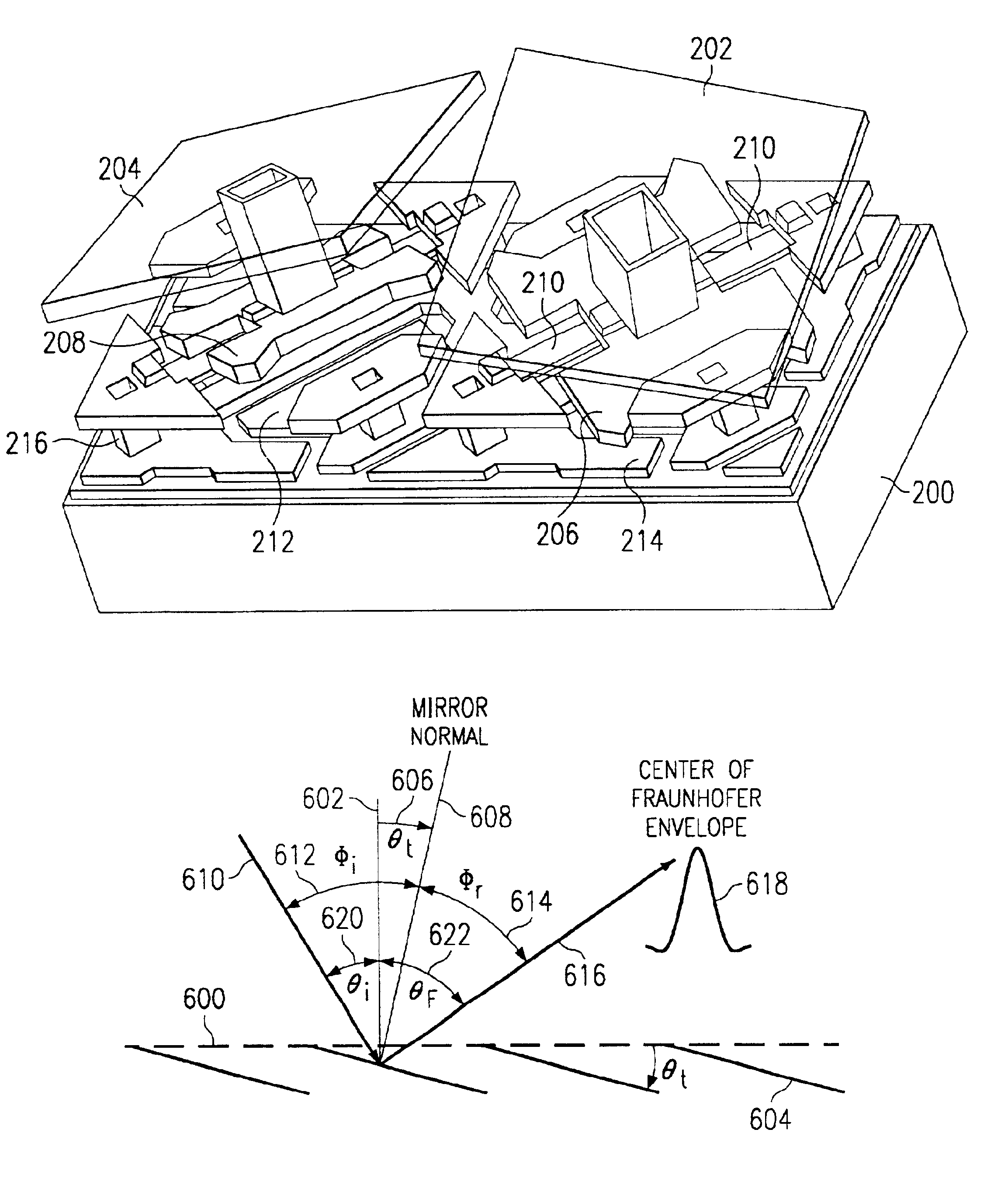
[0042]The use of MEMS devices, such as the DMD, in optical switching applications is complicated by diffraction effects. To use a typical DMD device, intended for use in a projection display application, in a near monochromatic spatially coherent switching application, may be extremely inefficient. This is because the near monochromatic spatially coherent light from a laser or optical amplifier, when reflected from the DMD, will likely be shared among several diffraction orders rather than being concentrated in a blazed condition as a single bright spot of light. For this reason, DMDs have not found a wide use in fiber optic / telecommunication applications. Fiber optic telecommunication networks can deploy single wavelength, coarsely populated multiple wavelength or densely populated multiple wavelength sources. For example, in wavelength division multiplexing (WDM) optical networking systems, the light being switched is made up of a number of single wavelength laser or amplified opt...


PUM


Abstract

A method for assuring a blazed condition in a DMD device used in telecommunications applications. By meeting certain conditions in the fabrication and operation of the DMD, the device can achieve a blazed condition and be very effective in switching near monochromatic spatially coherent light, thereby opening up a whole new application field for such devices. This method determines the optimal pixel pitch and mirror tilt angle for a given incident angle and wavelength of near monochromatic spatially coherent light to assure blazed operating conditions. The Fraunhofer envelope is determined by convolving the Fourier transforms of the mirror aperture and the delta function at the center of each mirror and then aligning the center of this envelope with a diffraction order to provide a blazed condition. The method of the present invention presents a formula for precisely determining the mirror pitch and tilt angle to assure that a blazed condition exists for a given incident angle and wavelength of near monochromatic spatially coherent light. Considerations for the special case, know as Littrow conditions, where the incident and the reflected light transverse the same path, are also given. This case is particularly attractive for fiber optic/telecommunication applications since the same optics can be used for incoming and outgoing (reflected) light.

Description

[0001]This application claims priority under 35 USC § 119(e)(1) of provisional application No. 60 / 223,366 filed Aug. 7, 2000.FIELD OF THE INVENTION[0002]The present invention relates to telecommunications switching apparatus and more particular to the use of two-dimensional blazed MEMS devices in such applications.BACKGROUND OF THE INVENTION[0003]Micromirror devices are micro-machined micro-electro-mechanical systems (MEMS), also known as micro-opto-electro-mechanical system (MOEMS). A typical micromirror device, or digital micromirror device (DMD) is comprises several hundred thousand mirrors, each approximately 16 μm square on a 17 μm grid. Each mirror is selectively able to rotate approximately 10 degrees in either a positive or negative direction about a torsion hinge.[0004]DMDs are widely used in display applications. In display applications, each mirror is used to control light destined for one pixel of a projected image. Since DMDs typically operate in either a full-on state,...

Claims


Application Information

Patent Timeline
Patent Type & Authority Patents(United States)
IPC IPC(8): G02B26/08G02B5/18
CPCG02B5/1828G02B26/0841
Inventor LEE, BENJAMIN L.TEW, CLAUDE E.DUNCAN, WALTER M.
Owner TEXAS INSTR INC
Why Eureka
Try Eureka