Linear adaptive optics system in low power beam path and method

a low-power beam and adaptive optics technology, applied in the field of optics, can solve the problems of reducing durability and/or increasing manufacturing costs, affecting the performance of conventional adaptive optics systems using deformable mirrors, and affecting the accuracy of high-power beams. to achieve the effect of facilitating the correction of aberration

Inactive Publication Date: 2010-09-16
RAYTHEON CO
View PDF10 Cites 49 Cited by
  • Summary
  • Abstract
  • Description
  • Claims
  • Application Information

AI Technical Summary

Benefits of technology

[0013]The need in the art is addressed by the system and method of the present invention. In the illustrative embodiment, the system includes a source of a first beam of electromagnetic energy; an amplifier for amplifying the beam to provide a second beam, a sensor for sensing aberration in the second beam and providing an error signal in response thereto; a processor for processing the error signal and providing a correction signal in response thereto; and a spatial light modulator responsive to the correction signal for adjusting the beam to facilitate a correction of the aberration thereof.
[0014]In more specific embodiments, source is a laser and the sensor is a laser wavefront sensor. A mirror is disposed between the modulator and the sensor for sampling the beam. The mirror has an optical thin-film dielectric coating on at least one optical s

Problems solved by technology

Unfortunately, the use of delicate optical devices in the path of a high-power beam is problematic.
Therefore, coatings may need to be applied at lower than optimal temperature using a less robust coating process, thereby reducing durability and/or increasing manufacturing cost.
In addition, conventional adaptive optics systems using deformable mirrors are limited in performance.
There is also a limitation with respect to the number actuators that can be used.
The stroke of the conventional deformable mirror is limited.
Further, a conventional continuous face sheet deformable mirror cannot correct for a pathology in the spatial phase pattern, such as a branch point or an abrupt phase discontinuity.
However, this scheme is practical only with a coherently-combined array of single-mode fiber ampl

Method used


Image

  • Linear adaptive optics system in low power beam path and method
  • Linear adaptive optics system in low power beam path and method
  • Linear adaptive optics system in low power beam path and method

Examples


Embodiment Construction

[0024]Illustrative embodiments and exemplary applications will now be described with reference to the accompanying drawings to disclose the advantageous teachings of the present invention.

[0025]While the present invention is described herein with reference to illustrative embodiments for particular applications, it should be understood that the invention is not limited thereto. Those having ordinary skill in the art and access to the teachings provided herein will recognize additional modifications, applications, and embodiments within the scope thereof and additional fields in which the present invention would be of significant utility.

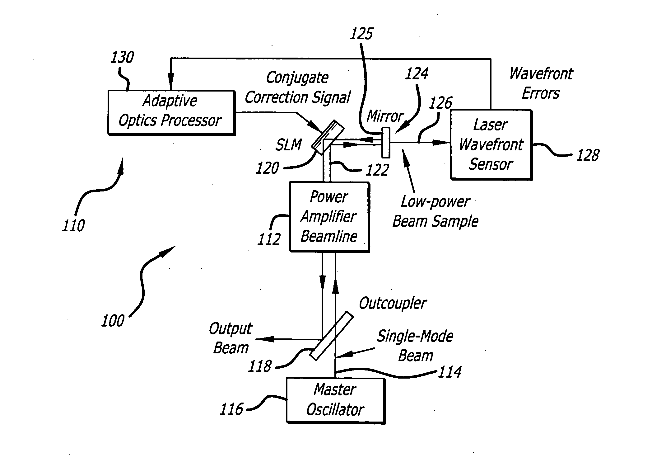
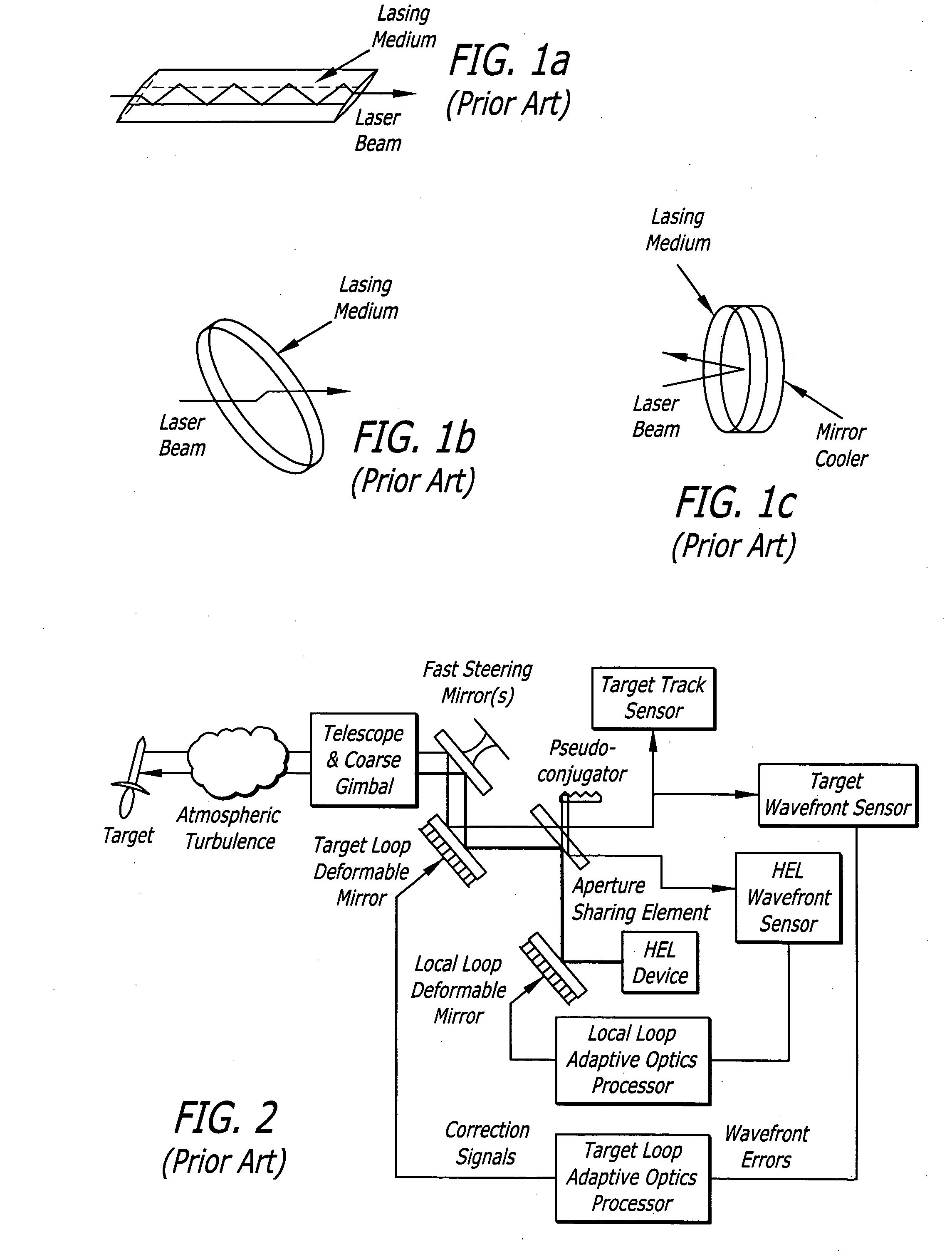
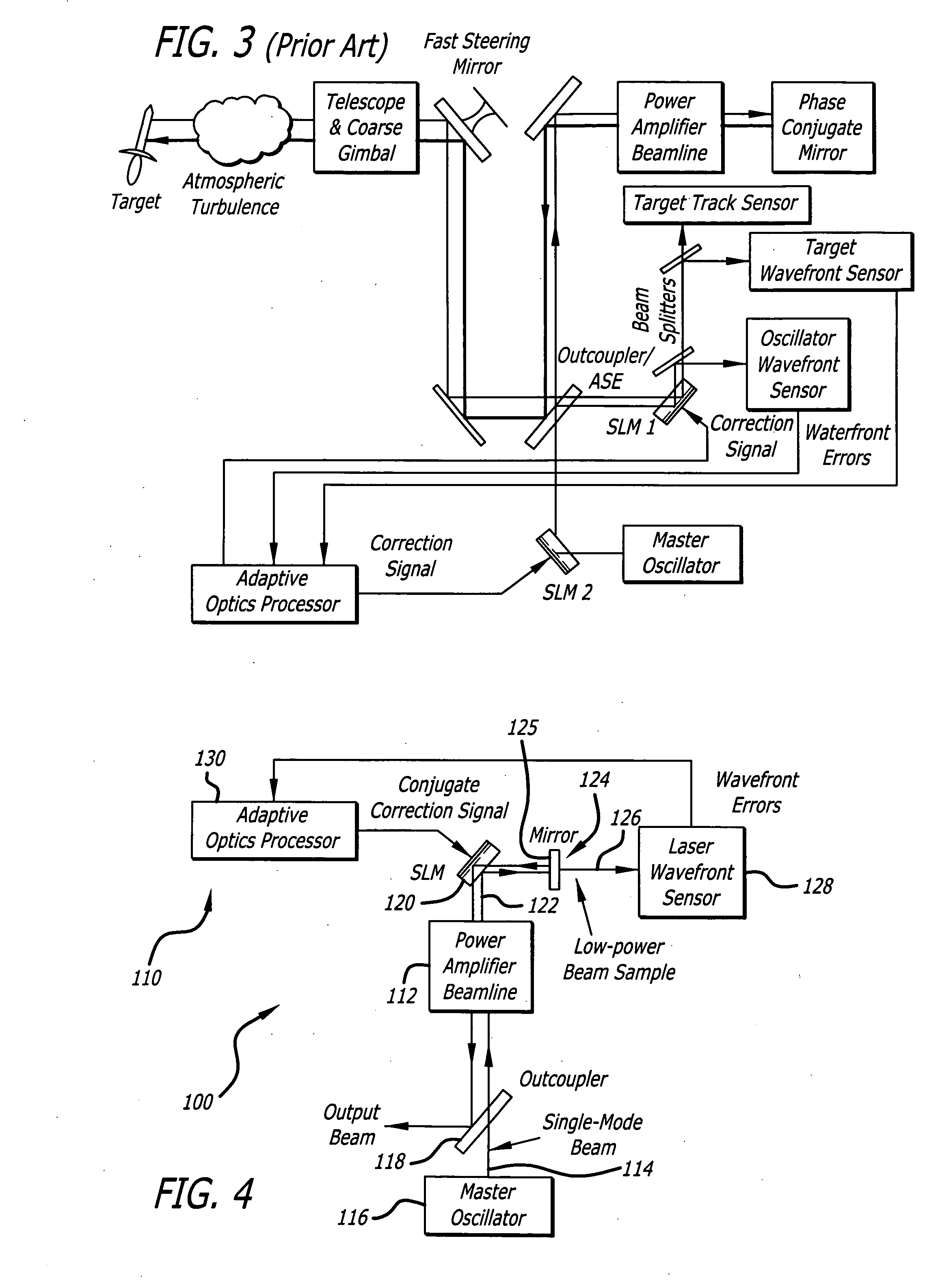
[0026]Traditional high power lasers rely on the geometry and thermal design of the laser medium and pumphead (cooling and support structure) to minimize the effects of thermally induced distortions on the beam quality of the laser. The most common geometries for high power bulk solid-state lasers are the parallelogram slab, disk, and active mirror, a...


PUM


Abstract

A system and method for providing a wavefront corrected high-energy beam of electromagnetic energy. In the illustrative embodiment, the system includes a source of a first beam of electromagnetic energy; an amplifier for amplifying said beam to provide a second beam; a sensor for sensing aberration in said second beam and providing an error signal in response thereto; a processor for processing said error signal and providing a correction signal in response thereto; and a spatial light modulator responsive to said correction signal for adjusting said beam to facilitate a correction of said aberration thereof. In more specific embodiments, the source is a laser and the sensor is a laser wavefront sensor. A mirror is disposed between said modulator and said sensor for sampling said beam. The mirror has an optical thin-film dielectric coating on at least one optical surface thereof. The coating is effective to sample said beam and transmit a low power sample thereof to said means for sensing aberration. The processor is an adaptive optics processor. The spatial light modulator may be a micro electro-mechanical system deformable mirror or an optical phased array. In the illustrative embodiment, the source is a master oscillator and the amplifier is a power amplifier beamline. An outcoupler is disposed between the oscillator and the amplifier.

Description

BACKGROUND OF THE INVENTION[0001]1. Field of the Invention[0002]The present invention relates to optics. More specifically, the present invention relates to systems and methods for directing and correcting high-power beams of electromagnetic energy.[0003]2. Description of the Related Art[0004]Directed energy weapons and specifically high-energy laser (HEL) weapons are being considered for variety of military applications with respect to a variety of platforms, e.g., spaceborne, airborne and land based systems to name a few. These weapons generally involve the use of the laser or other source of a high-power beam to track and destroy a target. To achieve mission objectives, directed energy weapons must be accurately steered and optimally focused. Steering involves line-of-sight control while focusing, with respect to HEL weapons, involves wavefront error correction. Currently, wavefront error correction is typically achieved using adaptive optics. The current state of the art in lase...

Claims


Application Information

Patent Timeline
IPC IPC(8): G02B26/00G02F1/01H01S3/13
CPCF41H13/005G02B26/06G02B27/0037H01S3/2333H01S3/005H01S3/1307H01S3/2308H01S3/0014F41G7/224
Inventor BYREN, ROBERT W.KING, WILLIAM B.FILGAS, DAVID M.
Owner RAYTHEON CO
Why Eureka
Try Eureka