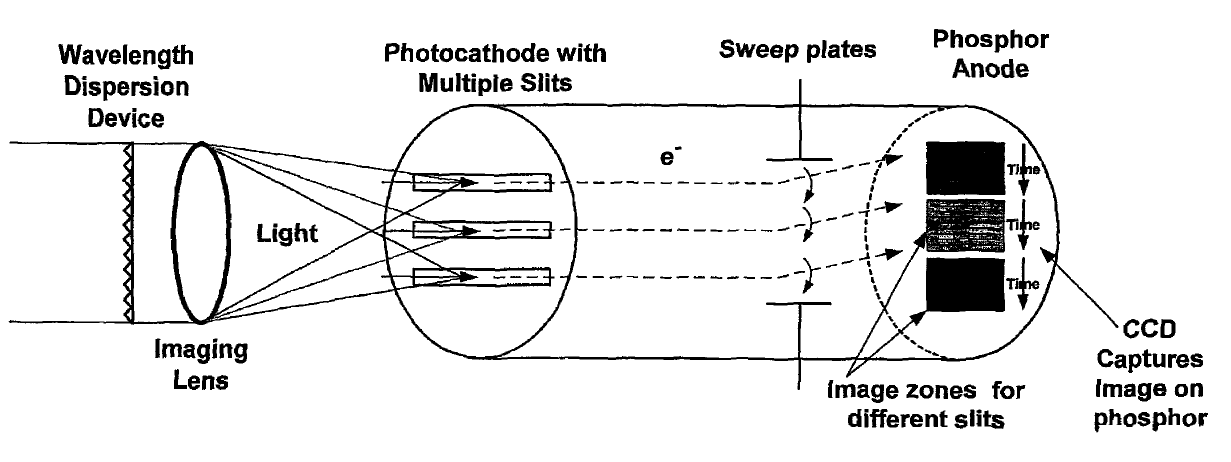
The other of the two dimensions, however, is unlike what an ordinary camera captures.
By the same token, however, such light when projected at very high powers can
pose a
hazard to people—and possibly to other creatures as well—who may be positioned to look directly at the source.
The possible
hazard is compounded by a like sensitivity to viewing specular reflections of the beam from the source.
Therefore the possibility of injury to eyes is an important obstacle to a new array of STIL devices.
It may be in part due to this problem that widespread commercial and industrial adaptations of the STIL principle have failed to appear in the marketplace.
Plainly this type of hardware is subject to several draw-backs.
Such devices are very expensive to make, maintain and use.
For field use, ruggedization is a necessary added expense (and a still-imperfect solution) since large vacuum tubes are inherently somewhat fragile.
Their external high-tension connections are not optimal for routine use in aircraft.
These devices too, unfortunately, are problematic and even ore so than the
electronic form.
The drawback of this approach as conventionally implemented is the requirement for the large high-speed rotating mirror, which is both bulky and relatively delicate.
What makes these drawbacks of the optical streaking technique particularly unfortunate is that streaking with an optical device would otherwise greatly expand the choices in commonly available detectors.
Regrettably the common detectors just mentioned are not suited for use as
photocathode materials, to generate electrons that can then be streaked inside a streak tube.
On the other hand it would accomplish nothing to place them following the conventional
photocathode—e. g. at the streak-tube
anode—since conversion from the optical to the electronic domain has already been accomplished at the
cathode.
For some
wavelength ranges this technique would be ideal—but the prior art has avoided these potential solutions because of the recognized problems presented by
spinning mirrors.
In its ability to fully
exploit these advantages, however, a conventional STIL is severely impaired by an overriding problem in streak lidar systems heretofore: inflexibility of pixel allocation.
This limitation may be appreciated from three different perspectives, although in a sense they are only different aspects of the common phenomenon:the STIL cannot
record in three dimensions without mechanical movement of the
measuring instrument relative to the region to be inspected;the only practical way to make optimally efficient use of the very expensive
detector area in a conventional STIL system is to build a
fiber-optic remapper; andeven when such a device has been built, a conventional STIL system fails to make fully economic use of that investment.
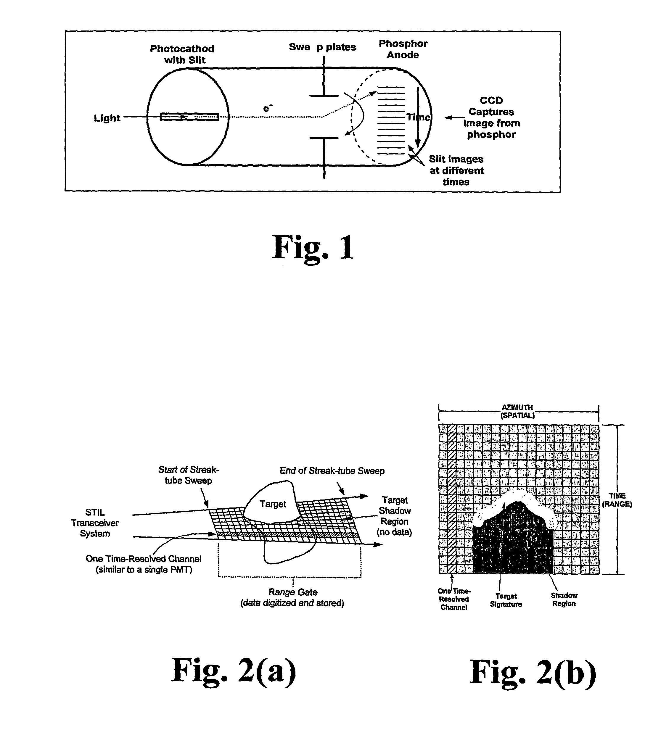
Range-gated systems have excellent transverse spatial resolution, but only have one range pixel per camera—which results in poor range resolution as suggested by the relatively tall volume elements (FIG.
Merely by way of example, one system well-known in this field as “Magic
Lantern” is forced to use six separate cameras to cover multiple depths, resulting in a large and expensive system.
Time-resolved systems, such as the one used in the advanced
receiver in ATD-111 (a
photomultiplier-tube-based, nonstreaking time-resolved lidar system), suffer from a similar contrast-reduction problem.
This system cannot isolate an object
signal, and moreover also collects a large area of water
backscatter around an object.
Unfortunately a frequency-doubled Q-switched Nd:YAG
laser (the primary
laser used in ocean lidar systems) operates efficiently only up to about 5 kHz.
Although this approach represents significant additional system complexity, it still does not resolve the significant degradation of detection SNR.
Unfortunately this powerful benefit of the STIL principle is not heretofore broadly available without mechanical movement of the
detector, and without costly and awkward remapping devices—and even then carries only very limited amounts of image information.
Inability of a conventional STIL instrument to fill this role is a major limitation in industrial and commercial uses.
This technique was severely limited in overall number of spatial pixels because of the relatively small number of pixels that can be mapped onto a slit.
At best, however, all such approaches are hampered by the costly custom fabrication required, and the need to manufacture a special unit for each desired mapping respectively.
This means that even after the limitation of expensive custom fabrication has been confronted and in a sense overcome by a decision to expend the necessary funds, and even after the requirement for making a separate special unit for each of several particular mappings has also been faced and in a sense overcome by a decision to invest even that multiple—yet nevertheless the technology continues to be not only uneconomic but also technically unsatisfactory because the resulting images carry inadequate, frustratingly small amounts of image information.
High-power short-pulse lasers are essential components of several different applications (e. g., laser trackers and imaging laser
radar); however, such lasers are notoriously unreliable.
It is difficult for vendors to manufacture them to desired specifications, and the devices seldom survive to their projected lifetime (at least at rated output power).
One of the most difficult aspects of the manufacture of such devices is the lack of
diagnostic equipment for the total characterization of the laser output.
Each of these instruments has significant limitations in the data that it produces.
Thus no one instrument provides information in time and space and phase with
high resolution in all dimensions.
After going through all of that analysis, however, laser designers have no way to compare the actually resulting, operating product with that
preliminary analysis.
These
detector systems are relatively slow (30 Hz to 10 kHz); while sufficient for assessing atmospheric corrections such detection naturally is inadequate for applications that require subnanosecond sample rates.
From the foregoing it will be clear that laser laboratory devices, and in particular WFS systems when used for laser evaluation, fail to satisfy the needs of laser developers.
This failure is a major problem, impeding progress in the design and refinement of more stable, reliable and long-lived lasers.
Even carried on a vehicle of modest size, practical forms of the system have relatively low data
throughput and may therefore require several measurement passes to acquire adequate data for a
region of interest.
These limitations represent additional problems because many applications would be better served by a system that a single person could carry, or that could survey and map a region in a
single pass—or ideally both.
(g) Limited uses of conventional streak lidar—No STIL packages fully suited for commercial or industrial surveillance and mapping are known to be on the market.
It appears that this may be due to a combination of factors including the visual hazards mentioned earlier (with the legal liability that would be associated with operations in populated areas), and also the limited data speed and resulting packaging obstacles outlined just above.
Terrestrial mapping is one function that can be performed using lidar, but this opportunity has not been exploited commercially.
Conventional STIL equipment, however, has not been set up (or at least not set up in a convenient format) for three-dimensional imaging.
Likewise it is not available with any kind of viewing redundancy, to surmount problems of temporary or local barriers to viewing.
Thus spectral,
fluorescence and polarization analyses in theory are susceptible to commercial and industrial streak-lidar beneficial exploitation.
Heretofore, however, necessary equipment adaptations for introducing
fluorescence, polarization and spectral analyses into streak lidar work—at least on a broad, general-use basis—have been unavailable.
The prior art in this field thus fails to teach how to go about making such refinements in any straight-forward, practical way.
This gap represents a major problem as it has left these kinds of mapping infeasible or even impossible—and accordingly several practical mapping needs unsolved.
More specifically, light in the visible, near-UV, and near-IR regions damages the
retina, while light in the far-UV and far-IR damages the
cornea; but light at about 1.5 microns tends to dissipate harmlessly in the
intraocular fluid between the
cornea and the
retina.
Traditional
photocathode materials are well suited at visible wavelengths; however, efficient photocathode detector materials do not exist for wavelengths much over one micron.
Unfortunately, S1 has very poor
quantum efficiency, which reduces the applicability for real-world imaging.
Due to the low efficiency of the S1 material, a 1.5-micron streak-lidar product based upon it would similarly operate inefficiently.
Pragmatically speaking, such a product would not be economic or viable.
Whether actually due to perceived lack of customer base or due to some failure in reduction to practice, no streak tube able to operate efficiently at 1.5 microns is currently available.
Again, pragmatically no successful report of testing is known.
No testing with a streak-tube photocathode, however, has been reported.
Nonlinear upconversion: Because conversion efficiency is a function of
optical power, nonlinear upconversion techniques such as SHG and SRS are not practical for low-level signals.
Also, because of
phase matching requirements these techniques are typically only efficient over limited fields of view.
At present a drawback of this technique, with respect to long-range streak-tube operations, is that the Raman
amplifier can be pulsed on for only 10 to 15 nsec at a time.
No demonstration, however, of pragmatically efficient operation in a lidar streak tube has been reported.
In the absence of dispositive testing, none of these appears to represent an enabling disclosure of a commercially feasible eye-safe STIL system.
Again, although well established these devices have not been associated with lidar
instrumentation heretofore.
As can now be seen, the related art remains subject to significant problems, and the efforts outlined above—although praiseworthy—have left room for considerable refinement.

