A new intracavitary tumor cryoablation catheter and its operating method

A technology for ablating catheters and tumors, applied in the field of medical devices, can solve the problems of increasing the difficulty and risk of implantation, balloon rupture, and easy deformation and folding of the balloon, so as to increase the cryoablation area, reduce the cold source pressure, The effect of increasing the contact area

Active Publication Date: 2018-05-04
NINGBO SHENGJIEKANG BIOTECH
View PDF10 Cites 0 Cited by
  • Summary
  • Abstract
  • Description
  • Claims
  • Application Information

AI Technical Summary

Problems solved by technology

For the cystic cavity, the distal end of the catheter is more required to be attached, and the distal end of the buffer unit of the patent is not fixed to the distal end of the balloon. The balloon lacks an overall support, and the balloon part lacks strong rigidity. When this structure enters some relatively narrow lumens or encounters resistance, the balloon is easily deformed and folded, and even friction with the buffer unit causes the balloon to rupture, which increases the difficulty and risk of placement

Method used


Image

  • A new intracavitary tumor cryoablation catheter and its operating method
  • A new intracavitary tumor cryoablation catheter and its operating method
  • A new intracavitary tumor cryoablation catheter and its operating method

Examples


specific Embodiment 2

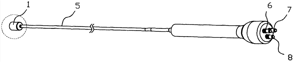
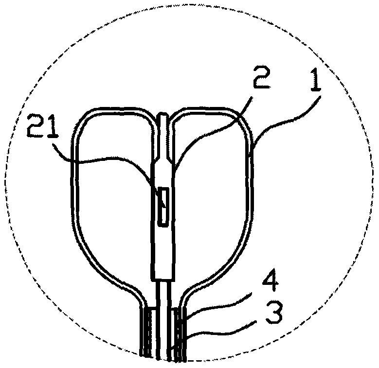
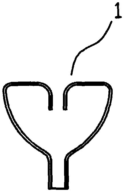
[0085] As shown in Figures 7 to 11, a new type of intracavitary tumor cryoablation catheter includes a balloon 1, an air intake line 3, a gas return line 4, a vacuum line 5, and a proximal end of the air intake line 3 that is sealed. The connected air inlet joint 6 , the return air joint 7 sealingly connected with the proximal end of the return air line 4 , and the vacuum joint 8 sealingly connected with the proximal end of the vacuum line 5 . The most distal end of the intracavitary tumor cryoablation catheter is the balloon 1, and the structure of the balloon 1 is the same as that of the specific embodiment 1, and will not be repeated here, as Figures 7a-7c As shown, the distal end of the balloon 1 is sealingly connected with the distal end of the buffer unit 2, for example, the distal end of the balloon 1 is turned inward first, and then the buffer unit 2 is inserted into the buffer unit 2. In the balloon 1, the distal end of the buffer unit 2 is sealed and connected to th...

specific Embodiment 3

[0087] As shown in Figures 12 to 16, a new type of intracavitary tumor cryoablation catheter includes a balloon 1, an air intake line 3, a gas return line 4, a vacuum line 5, and a proximal end of the air intake line 3 that is sealed. The connected air inlet joint 6 , the return air joint 7 sealingly connected with the proximal end of the return air line 4 , and the vacuum joint 8 sealingly connected with the proximal end of the vacuum line 5 . The most distal end of the intracavitary tumor cryoablation catheter is the balloon 1, and the structure of the balloon 1 is the same as that of the specific embodiment 1, and will not be repeated here, as Figures 12a-12c As shown, the distal end of the balloon 1 is sealingly connected with the distal end of the buffer unit 2, and a fixing sleeve 26 is arranged outside the connection, and the inner wall of the fixing sleeve 26 is in contact with the balloon 1 and the buffer unit 2. The outer wall of the connection point of the buffer u...


PUM


Abstract

The invention relates to a novel intraluminal tumor cryoablation catheter and an operation method thereof. The catheter comprises a balloon, an air intake pipeline, a return air pipeline, a vacuum pipeline, and proximal ends respectively connected to the intake pipeline, the return air pipeline and the vacuum pipeline. The air inlet joint, the air return joint and the vacuum joint are sealed and connected, and the vacuum pipeline is located outside the intake pipeline and the return gas pipeline. The conduit also includes a buffer unit, and the buffer unit is arranged at the far end of the inlet pipeline and is set In the balloon, the buffer unit is provided with a buffer air outlet, the proximal end of the buffer unit is sealedly connected with the distal end of the air intake pipeline or the air return pipeline, the distal surface of the balloon is concave, and the distal end of the buffer unit is far away from the balloon. The end is sealed and connected, and the connection point between the distal end of the buffer unit and the balloon is arranged in the middle of the inner recess of the distal end of the balloon or inside the distal end of the balloon. The catheter can cooperate with the endoscope to adapt to the complex cavity environment, and the distal end of the balloon has a larger contact area to ensure that it has a larger freezing range.

Description

technical field [0001] The invention belongs to the field of medical devices, and in particular relates to a novel intracavity tumor cryoablation catheter and an operating method thereof. Background technique [0002] Since Cooper created the liquid nitrogen cryotherapy device in 1963, it has achieved remarkable results through clinical application. For more than half a century, a novel medical method-cryogenic surgery has been widely used clinically at home and abroad. In the early 1980s, low-temperature surgical technology was introduced into China. Hospitals or medical research departments in various regions combined with local scientific research units or factories to independently design and develop a batch of experimental prototypes of various types of low-temperature surgical instruments, the most common of which are The most popular is the hand-held and hose cabinet-type liquid nitrogen cryotherapy device, which is provided to hospitals for clinical popularization of...

Claims


Application Information

Patent Timeline
Patent Type & Authority Patents(China)
IPC IPC(8): A61B18/02
Inventor 吕世文姜昊文戚迪波邢宗江刁月鹏
Owner NINGBO SHENGJIEKANG BIOTECH
Why Eureka
Try Eureka