Vertical supporting device

A technology of vertical support and mounting rods, applied in metal processing, metal processing equipment, manufacturing tools, etc., can solve the problems of unable to bear radial force, large size, poor rigidity, etc., achieve good orientation and rigidity, and avoid force Good deformation and support effect

Inactive Publication Date: 2015-09-16
WENZHOU UNIVERSITY
View PDF5 Cites 4 Cited by
  • Summary
  • Abstract
  • Description
  • Claims
  • Application Information

AI Technical Summary

Problems solved by technology

[0002] In aviation industry manufacturing and other industries, when large parts are manufactured and assembled, the attitude of the parts needs to be adjusted during the production process. The commonly used attitude adjustment method is to arrange three three-coordinate adjustment devices under the parts, among which the vertical The structure of the support device in the direction is connected in series by a servo motor, a coupling, a screw, and a support column. The support column is connected with the screw nut. When the screw rotates, the nut moves in a straight line, driving the support column to move, and its vertical dimension Large, poor rigidity, can not bear radial force, can not be directly used for vertical support, can not meet the use requirements in some occasions with height and rigidity requirements

Method used


Image

  • Vertical supporting device
  • Vertical supporting device
  • Vertical supporting device

Examples


Embodiment Construction

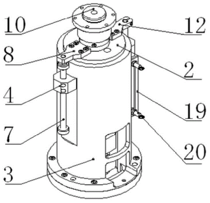
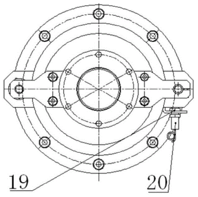
[0019] Such as Figure 1~3 As shown, the vertical support device includes an inner guide seat 1 and an outer guide sleeve 3 placed on its outer layer, and a guide column 2 that can slide along its axial direction is provided between the inner guide seat 1 and the outer guide sleeve 3, The end of the inner guide seat 1 is equipped with a motor mounting seat 14, the servo electric cylinder 18 is placed in the inner guide seat 1 and fixed with the motor mounting seat 14, the connecting seat 11 is installed on the guide column 2, and the servo electric cylinder push rod and The connection base 11 is connected, and a support ball head 9 is installed on the connection base 11, and the support ball head 9 is placed on the ball socket support base 10 to form a ball joint floating support; an anti-rotation connecting plate 12 is fixed on the guide column 2, and the outer guide sleeve An anti-rotation seat 15 is fixed on the side wall of 3, an anti-rotation rod 16 arranged parallel to t...


PUM


Abstract

The invention relates to a vertical supporting device which comprises an inner guiding base and an outer guiding sleeve located on the outer layer of the inner guiding base, wherein a guiding pillar which can slide along the axial direction is disposed between the inner guiding base and the outer guiding sleeve, a motor installation base is installed on the end part of the inner guiding base, a servo electric cylinder is placed inside the inner guiding base and fixed with the motor installation base, a connecting base connected with a push rod of the servo electric cylinder is installed on the guiding pillar, a supporting bulb is installed on the connecting base, and the supporting bulb is placed on a ball socket supporting base to form ball joint floating supporting; and an anti-rotation connecting plate is fixed on the guiding pillar, an anti-rotation base is fixed on the side wall of the outer guiding sleeve, an anti-rotation rod is disposed in parallel with the axial direction of the push rod of the servo electric cylinder, one end of the anti-rotation rod is fixed on the anti-rotation base, and the other end passes through a guiding hole in the anti-rotation base. A guiding part and a transmission part coincide at positions and heights, and both the inner guiding and the outer guiding are adopted in the guiding pillar to keep good guiding performance and rigidity. As vertical guiding, the guiding pillar has large rigidity, so that guiding deviation caused by force carrying does not take place.

Description

technical field [0001] The invention relates to a vertical support device, which is used for vertical attitude adjustment of a component mounting surface. Background technique [0002] In aviation industry manufacturing and other industries, when large parts are manufactured and assembled, the attitude of the parts needs to be adjusted during the production process. The commonly used attitude adjustment method is to arrange three three-coordinate adjustment devices under the parts, among which the vertical The structure of the support device in the direction is connected in series by a servo motor, a coupling, a screw, and a support column. The support column is connected with the screw nut. When the screw rotates, the nut moves in a straight line, driving the support column to move, and its vertical dimension Large, poor rigidity, can not bear radial force, can not be directly used for vertical support, and cannot meet the use requirements in some occasions with height and ...

Claims


Application Information

Patent Timeline
Patent Type & Authority Applications(China)
IPC IPC(8): B23P19/10
CPCB23P19/10
Inventor 冯爱新薛伟张华夏仲秋许兴旺李峰平吴浩张津超
Owner WENZHOU UNIVERSITY
Why Eureka
Try Eureka