Driving mechanism of electric main shaft lock blade

A technology of driving mechanism and electric spindle, which is applied in the direction of metal processing machinery parts, clamping, support, etc., can solve the problems of prolonged tool change time and long control time, and achieve the effect of improving production efficiency and shortening control auxiliary time

Inactive Publication Date: 2015-09-16
HUBEI UNIV OF AUTOMOTIVE TECH
View PDF11 Cites 4 Cited by
  • Summary
  • Abstract
  • Description
  • Claims
  • Application Information

AI Technical Summary

Problems solved by technology

It is especially important to reduce the time of loosening and locking the knife as much as possible! At present, many machining centers use hydraulic drive to realize the tool release and lock of the electric spindle, but because the control of the hydraulic cylinder needs to rely on the PLC and the travel switch, the next action can only be performed after receiving the position signal of the travel switch, which will take a long time. The control time is longer, so that the tool change time is lengthened

Method used


Image

  • Driving mechanism of electric main shaft lock blade
  • Driving mechanism of electric main shaft lock blade

Examples


Embodiment Construction

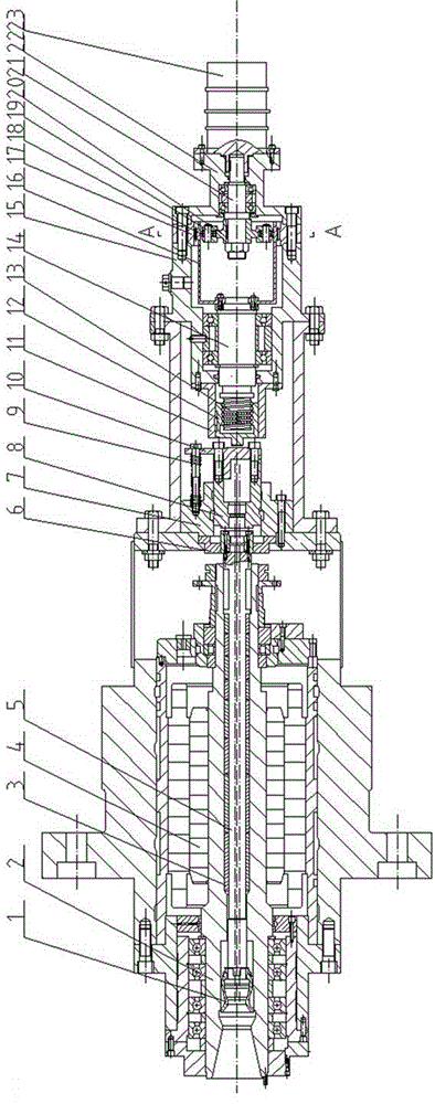
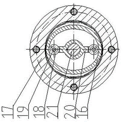
[0014] Such as figure 1 , 2 as shown, figure 1 is the main sectional view of the mechanism of the present invention; figure 2 yes figure 1 The sectional view along A-A shows the meshing relationship between the flexible spline and the rigid spline of the harmonic reducer.

[0015] Such as figure 1 As shown, in order to describe the electric spindle tool locking drive mechanism, the prior art (electric spindle) tool locking device structure is first described: mainly including claw 1, main shaft 2, disc spring 3, rotor 4, pull rod 5, thrust shaft 6. Support body 7, sliding shaft 8, spring 9, push plate 10 (deleted is not the prior art); the front and rear ends of the main shaft 2 are supported by multiple bearings; It can freely rotate around the axis of the main shaft 3 under driving; the pull rod 5 passes through the center of the main shaft 3, and the left end of the pull rod 5 is connected with the claw 1, and the right end is connected with the thrust shaft 6; 3 The...


PUM


Abstract

The invention puts forward a driving mechanism of an electric main shaft lock blade, which comprises a motion actuator, a harmonic reducing mechanism and an unlocking blade servo motor, wherein the unlocking blade servo motor drives the harmonic reducing mechanism, and the motion actuator has the structure that a ball screw rod is processed on a low-speed shaft of the harmonic reducing mechanism, the ball screw rod is matched with a screw rod nut, and the screw rod nut is connected to a slide sleeve by a guiding key; and a push plate is connected to a slide shaft by screws, and the upper part of the push plate is connected to a supporting body by screws and a spring in order to separate the slide shaft from a push shaft. The harmonic reducing mechanism drives the motion actuator, and pushes a pull rod and a jaw of the driving mechanism of the electric main shaft lock blade to move to left so as to realize blade unlocking; and the low-speed shaft is driven by reverse rotation of a flexible gear of the harmonic reducing mechanism, the motion actuator is then driven to return, and the pull rod of the driving mechanism of the electric main shaft lock blade is returned under force of a belleville spring to realize blade locking. The driving mechanism of the electric main shaft lock blade provided by the invention drives the pull rod by the unlocking blade servo motor, the harmonic reducing mechanism and the motion actuator and finally realizes the purpose of quick blade changing.

Description

technical field [0001] The invention relates to an electric spindle tool locking mechanism of a high-speed machining center, in particular to a servo-driven electric spindle tool locking mechanism. Background technique [0002] High-speed machining center is a typical product of high-speed machine tools, and high-speed machining technology has attracted more and more people's attention. In order to realize the high efficiency of the machine tool, the high speed of the automatic tool changer (ATC), which is one of the important components of the machining center, has also become an important technical content of the high-speed machining center, and the requirements for the tool change time are also gradually increasing. Time is an important indicator of high-efficiency machining centers. It is especially important to reduce the time of loosening and locking the knife as much as possible! At present, many machining centers use hydraulic drive to realize the tool release and ...

Claims


Application Information

Patent Timeline
Patent Type & Authority Applications(China)
IPC IPC(8): B23Q3/157
CPCB23Q3/15553B23Q3/157Y02P70/10
Inventor 邱新桥杨斌
Owner HUBEI UNIV OF AUTOMOTIVE TECH
Why Eureka
Try Eureka