
Pushing and blocking mechanism used during forklift discharging

A technology for a propulsion mechanism and a forklift, applied in the direction of a hoisting device, etc., can solve the problems of high labor intensity, low operation efficiency, time-consuming and labor-intensive, etc., and achieve the effects of flexible and reliable movements, improved operation efficiency, and simple overall structure.

Inactive Publication Date: 2015-09-16
林成富 +1
View PDF6 Cites 0 Cited by
  • Summary
  • Abstract
  • Description
  • Claims
  • Application Information

AI Technical Summary

Problems solved by technology

The method of lifting and lowering the base and the goods at the same time is not suitable for layer-by-layer stacking operations, because there is a base below, and the upper base cannot be taken out, but can only be sandwiched between the goods
In order to solve the above problems, some leave a gap on the base, such as Figure 4 , 5 , shown in 6: the base includes a chassis 30, there are support plates 31 arranged in parallel on the chassis 30, there is a gap 32 between adjacent support plates 31, the goods are stacked on the support plate 31, and the forks are inserted from the gap 32 during operation. When the fork tines are lifted up, only the goods are lifted, and the base is not lifted accordingly. However, when the forks are falling, the fork tines are pressed down by the goods on them. When the fork is pulled back, the goods follow; some work directly by manual operation; time-consuming, labor-intensive, and low-efficiency

Method used


Image

  • Pushing and blocking mechanism used during forklift discharging
  • Pushing and blocking mechanism used during forklift discharging
  • Pushing and blocking mechanism used during forklift discharging

Examples


Embodiment 1

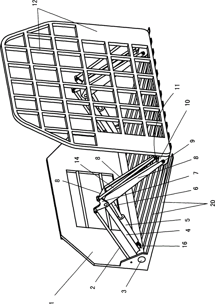
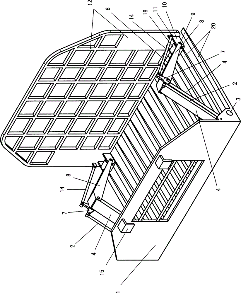
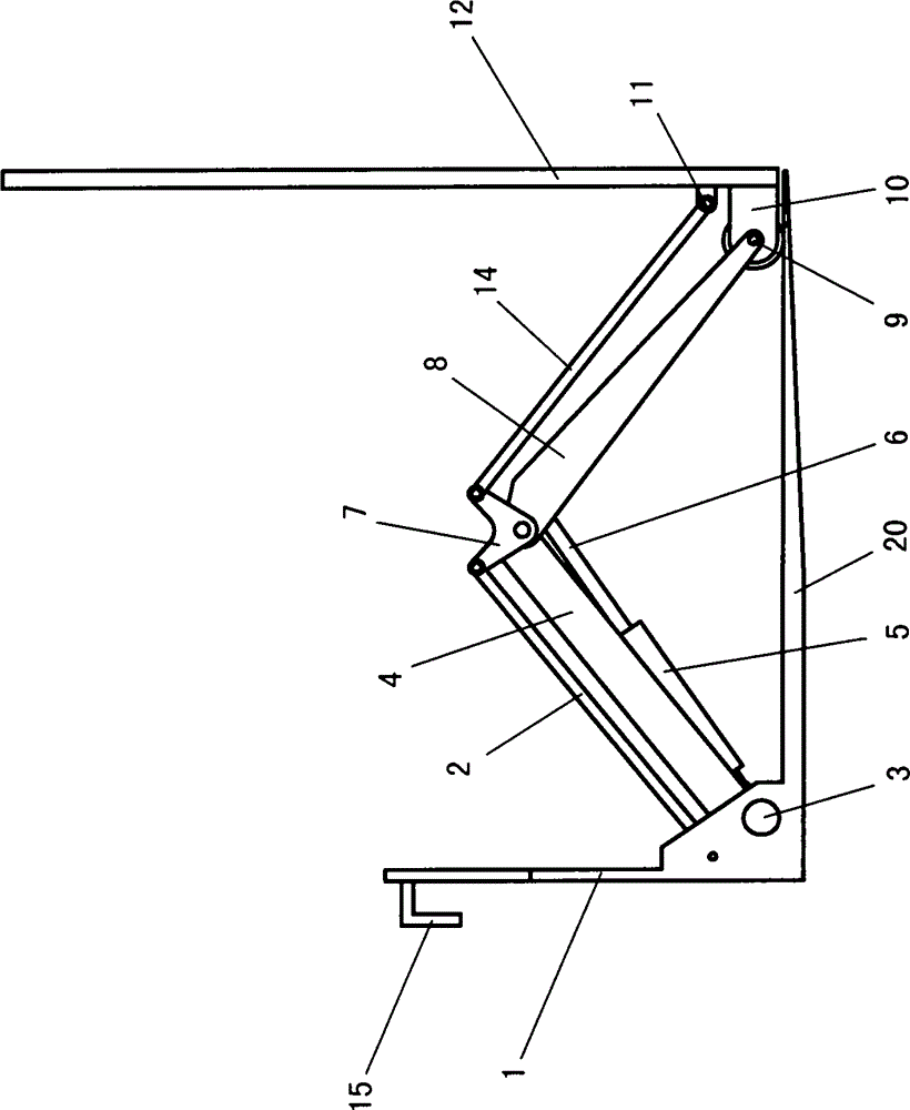
[0035] like figure 1 , 2 , shown in 3, 8: 1 is to hang the hanging plate that vertically arranges, and a plurality of mutually parallel fork tines 20 are fixedly connected on the lower side of hanging plate 1. On the fork tine 20 is seated a push block plate 12 arranged vertically. The lower bracket 10 is welded on the lower side of the push baffle plate 12, and the lower bracket 10 is equipped with a roller 18 through the lower pin shaft 9. The push baffle plate 12 is seated on the fork teeth 20 through the roller 18. There are two rollers 18, and they are respectively located on Push baffle plate 12 lower sides both sides.

[0036] A translational pushing mechanism is arranged between the push plate 12 and the hanging plate 1 , and the translational pushing mechanism includes a first connecting rod 2 , a second connecting rod 4 , a third connecting rod 8 , a fourth connecting rod 14 , and a connecting plate 7 .

[0037] The specific structure of the translational pushing...

Embodiment 2

[0049] like Figure 9 ~ Figure 17 As shown: the difference from Embodiment 1 is that a plurality of mutually parallel fork tines 20 are arranged in an arc-shaped projection on a plane perpendicular to the longitudinal direction of the fork tines 20, and the fork tines located in the middle are lower than the fork tines on both sides, forming Concave distribution structure (such as Figure 12 , Figure 13 ). The height of the support plate 31 on the base that cooperates with it changes thereupon, promptly the support plate 31 that is positioned at the center is the shortest, and the support plate 31 on both sides is the highest, forms the arc that is now toward concave, coincides with each fork tine distribution (such as Figure 15 , Figure 16 , Figure 17 ). During operation, after forking up the goods stacked on the support plate 31, the underside of the goods also forms an arc, and then when stacking, it can be guaranteed to match the arc formed on the stacked goods, e...

Embodiment 3

[0051] like Figure 18-22 Shown: different from embodiment 2 is that a plurality of mutually parallel fork tines 20 are arranged in a wave shape when projected on a plane perpendicular to the longitudinal direction of the fork tines 20, and the bottom has two troughs, and the two troughs are a crest ( like Figure 21 ). The height of the support plate 31 on the base that cooperates with it changes thereupon, and the height of the support plate 31 is wave-shaped (as in the cross-section of each support plate) Figure 22 ). During operation, after forking up the goods stacked on the support plate 31, the underside of the goods also forms an arc, and then when stacking, it can be guaranteed to match the arc formed on the stacked goods, ensuring the stability of the goods stacking , It also ensures that the space in the container is fully utilized.


PUM


Abstract

The invention discloses a pushing and blocking mechanism used during forklift discharging. The mechanism is used for pushing and blocking goods to prevent stacked goods from toppling over when fork prongs used for forking goods are retracted after goods are stacked during goods stack-loading with a forklift. The mechanism comprises a vertically arranged hanging plate, wherein multiple parallel fork prongs are connected to one side of the lower side of the hanging plate, a vertically arranged pushing and blocking plate is located on the fork prongs, a horizontal movement pushing mechanism is arranged between the pushing and blocking plate and the hanging plate, and a hook is arranged on the upper side of the other side of the hanging plate. The mechanism is simple in overall structure, flexible and reliable in movement, and capable of saving time and labor, relieving the labor intensity of workers and improving working efficiency.

Description

technical field [0001] The invention relates to a pushing mechanism, in particular to a forklift unloading pushing mechanism, which is used to push the goods during the process of stacking the goods by the fork tines of the forklift when the goods are stacked and then withdrawn to the fork tines. block to prevent stacked goods from dumping. Background technique [0002] At present, in the process of cargo shipment, forklifts are widely used for operations. There are at least two parallel fork tines in a row at the front of the forklift. The fork tines are inserted into the bottom surface of the cargo, and then moved upward to lift the cargo, and then walk to the appropriate position. , drop the tines, and put the goods down. There are two situations in this way of operation. One is that the goods are stacked on the base, and the fork of the forklift is inserted into the base. When the base is lifted, the base rises together with the goods on it. The teeth are ready and the...

Claims


Application Information

Patent Timeline
Patent Type & Authority Applications(China)
IPC IPC(8): B66F9/19
CPCB66F9/19
Inventor 林成富宋明君
Owner 林成富
Learn More