Square tool table pushing, positioning and clamping mechanism for lathe

A square tool post, positioning and clamping technology, used in positioning devices, clamping, metal processing mechanical parts, etc., can solve the problems of low workpiece machining accuracy, inability to save costs, and high cost of space occupation

Active Publication Date: 2014-05-28
通用技术集团大连机床有限责任公司
View PDF7 Cites 10 Cited by
  • Summary
  • Abstract
  • Description
  • Claims
  • Application Information

AI Technical Summary

Problems solved by technology

[0002] There are grooves around the outside of the square tool table assembled on the lathe. When processing the groove, the square tool table needs to be clamped. Usually, the workpiece clamping is completed by the clamping cylinder and the auxiliary pushing cylinder. This form of fixture occupies the space cost It is tall and high, and the manual combined fixture composed of the pressure plate and bolts used in manual clamping is fixed on the ordinary machine tool workbench through the T-shaped slot when in use, and the workpiece is manually clamped after the workpiece is installed, and the clamping force and clamping position are manually controlled. , strong randomness, resulting in low workpiece machining accuracy
Neither of the above two methods can achieve the purpose of saving cost and completing workpiece clamping well.

Method used


Image

  • Square tool table pushing, positioning and clamping mechanism for lathe
  • Square tool table pushing, positioning and clamping mechanism for lathe
  • Square tool table pushing, positioning and clamping mechanism for lathe

Examples


Embodiment Construction

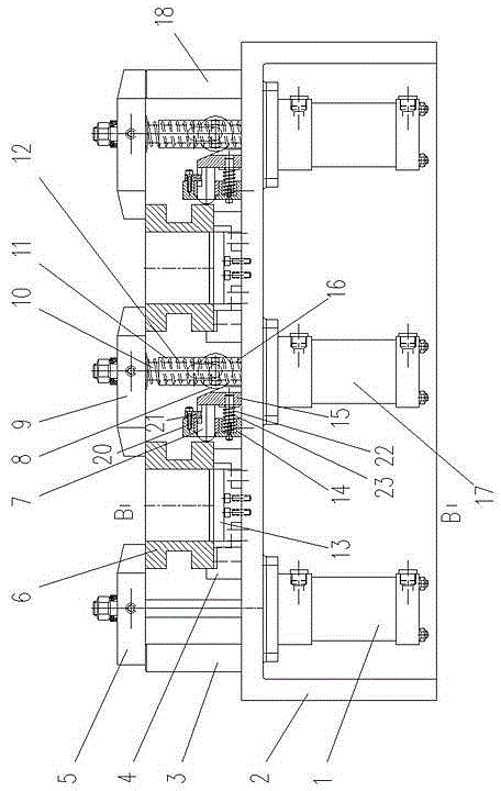
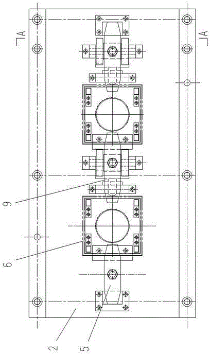
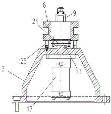
[0013] Such as figure 1 , 2 , shown in 3, 4, 5, 6: 2 is a frame, on the frame 2 vertically arranged with the side oil cylinder 1 that is positioned at both sides and the middle oil cylinder 17 that is positioned at the middle that joins with hydraulic control device. The upper end of the piston rod matched with the side oil cylinder 1 is rotatably connected with a side pressing plate 5 through a pin shaft, and the upper end of the middle piston rod 10 matched with the middle oil cylinder 17 is rotatably connected with an intermediate pressing plate 9 through a pin shaft.

[0014] On the frame 2, the two sides of the middle parts of the adjacent two piston rods are fixedly connected with the support block 25 supporting the square tool table 6 by screws, and the left side is fixedly connected with the platform 4 by screws.

[0015] A slide block 24 is provided on the frame 2, and the slide block 24 and the top of the frame 2 slide in a dovetail groove manner. The insert block ...


PUM


Abstract

The invention relates to a square tool table pushing, positioning and clamping mechanism for a lathe. The square tool table pushing, positioning and clamping mechanism comprises a framework. Side cylinders and an intermediate cylinder which are connected with a hydraulic control device are vertically arranged on the framework. Side pressing plates are rotationally connected to the upper ends of piston rods matched with the side cylinders. An intermediate pressing plate is rotationally connected at the upper end of an intermediate piston rod matched with the intermediate cylinder. Support blocks for supporting a square tool table are fixed on two sides of the intermediate portion of the two adjacent piston rods on the framework, and a rest table is fixed on the left side of the same. A slider is arranged on the framework, and an insert for being inserted into an inner hole of the square tool table is fixed above the slider. A left auxiliary support is arranged at the left end of the framework, and a right auxiliary support is arranged at the right end. A pushing mechanism pushing the square tool table to the rest table is arranged on the framework. The square tool table pushing, positioning and clamping mechanism is simple in integral structure, flexible and reliable to act, small in occupation space, low in manufacturing cost, firm to clamp and good in stability.

Description

technical field [0001] The invention relates to a clamping mechanism, in particular to a clamping mechanism for positioning and pushing a square tool table for a lathe. Background technique [0002] There are grooves around the outside of the square tool table assembled on the lathe. When processing the groove, the square tool table needs to be clamped. Usually, the workpiece clamping is completed by the clamping cylinder and the auxiliary pushing cylinder. This form of fixture occupies the space cost It is tall and tall, and the manual combined fixture consisting of a pressure plate and bolts used in manual clamping is fixed on the ordinary machine tool workbench through a T-shaped slot when in use, and the workpiece is manually clamped after the workpiece is installed, and the clamping force and clamping position are manually controlled. , strong randomness, resulting in low machining accuracy of the workpiece. Neither of the above two methods can achieve the purpose of c...

Claims


Application Information

Patent Timeline
Patent Type & Authority Applications(China)
IPC IPC(8): B23Q3/08
CPCB23Q3/082
Inventor 刘佳奇宁甲亮邢晓辉陈士有赵凯张超
Owner 通用技术集团大连机床有限责任公司
Why Eureka
Try Eureka