Bag clamping mechanism in automatic bagging machine

A bag machine and bag clamping technology, which is applied in the field of gravity automatic loading weighing apparatus, can solve the problems of loose structure and poor action reliability, and achieve the effect of synchronous action, flexible and reliable action, and simple structure

Active Publication Date: 2012-01-04
WUXI NAITE ELECTROMECHANICAL INTEGRATING TECH
View PDF9 Cites 11 Cited by
  • Summary
  • Abstract
  • Description
  • Claims
  • Application Information

AI Technical Summary

Problems solved by technology

This kind of structure is loose, and the action reliability is poor, so it is not suitable for use on automatic bagging equipment

Method used


Image

  • Bag clamping mechanism in automatic bagging machine
  • Bag clamping mechanism in automatic bagging machine
  • Bag clamping mechanism in automatic bagging machine

Examples


Embodiment Construction

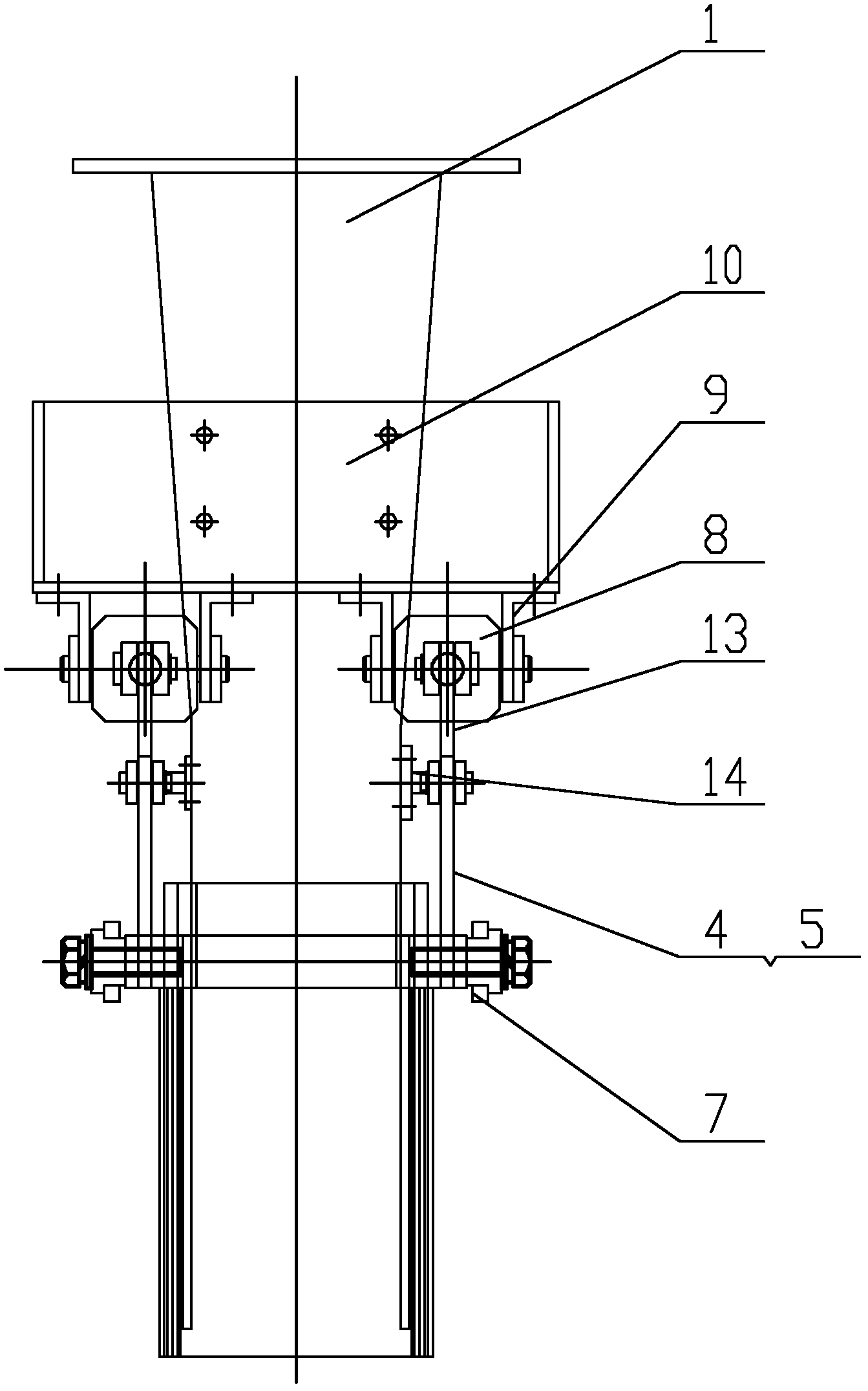
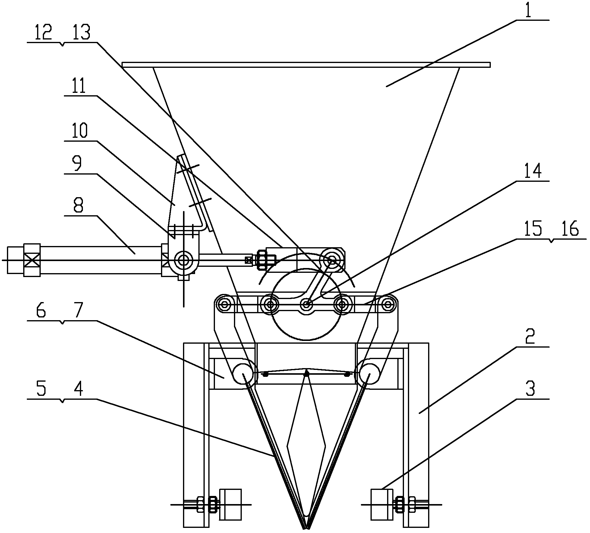
[0010] Such as Figure 1 ~ Figure 2 Shown: Including inverted cone-shaped hopper body 1, bag holder 2, tendon anti-collision block 3, left valve 4, right valve 5, valve support 6, sliding bearing 7, cylinder 8, cylinder mounting frame 9, bracket 10. Cylinder connector 11 , first pin shaft 12 , three-arm connecting rod 13 , rotating shaft 14 , connecting rod 15 and second pin shaft 16 .

[0011] The present invention is mainly made up of lower hopper, left and right valves and cylinder driving mechanism.

[0012] The lower hopper includes an inverted conical lower hopper body 1, a bag holder 2, and a beef tendon anti-collision block 3; wherein the bag holder 2 is welded to the lower end of the lower hopper body 1, and the beef tendon anti-collision block 3 is connected to the bag by bolts on the stand.

[0013] The left and right valves include a left valve 4, a right valve 5, a valve support 6, and a sliding bearing 7; wherein the valve support 6 is fixed on the bag support ...


PUM


Abstract

The invention relates to a bag clamping mechanism in an automatic bagging machine. For the bag clamping mechanism, bag clasping supports are welded on the lower end of a discharge hopper body; valve bearings are fixed on the bag clasping supports by bolts; a left valve and a right valve are respectively hinged on the valve bearings by bolts through a sliding bearing; the supports are arranged on the discharge hopper by bolts; cylinder mounting frames are arranged on the supports by bolts; cylinders are hinged on the cylinder mounting frames; cylinder connection pieces are connected on ends ofcylinder piston rods by threads; a center hole of a three-arm connection rod is sheathed on a rotating shaft; the rotating shaft is arranged on the discharge hopper body by bolts; the cylinder connection pieces are hinged with one end of the three-arm connection rod through a first pin shaft; and the other two ends of the three-arm connection rod are respectively connected with the left valve andthe right valve through a connection rod and a second pin shaft. The bag clamping mechanism has the advantages of simple, compact and reasonable structure, and is flexible and reliable in action, wherein, the left valve and the right valve work synchronously, thus being applicable to the automatic bagging equipment.

Description

technical field [0001] The invention relates to a bag clamping mechanism in an automatic bag loading machine, in particular to an automatic bag loading machine in weighing and packaging equipment, and belongs to the technical field of gravity automatic loading scales. Background technique [0002] In the traditional bag clamping mechanism, horizontally opposed cylinders are used to push the bag clamping device to clamp the packaging bag on the discharge port. This kind of structure is loose, and the action reliability is poor, so it is not suitable for use on automatic bagging equipment. Contents of the invention [0003] The object of the present invention is to overcome the above disadvantages, thereby providing a bag clamping mechanism in an automatic bag loading machine, the bag clamping mechanism is flexible and reliable, and the left and right valves move synchronously, which is suitable for use on automatic bag loading equipment. [0004] According to the technical...

Claims


Application Information

Patent Timeline
Patent Type & Authority Applications(China)
IPC IPC(8): B65B43/54
Inventor 张晓传
Owner WUXI NAITE ELECTROMECHANICAL INTEGRATING TECH
Why Eureka
Try Eureka