
Camera module set support and camera module set with same

A camera module and image sensing technology, applied in image communication, camera body, color TV parts and other directions, can solve the problems of difficult to remove debris, glue needle hitting electronic components, affecting imaging effect, etc. To achieve the effect of ensuring the quality of imaging

Active Publication Date: 2015-09-16
NANCHANG OFILM HUAGUANG TECH CO LTD
View PDF7 Cites 12 Cited by
  • Summary
  • Abstract
  • Description
  • Claims
  • Application Information

AI Technical Summary

Problems solved by technology

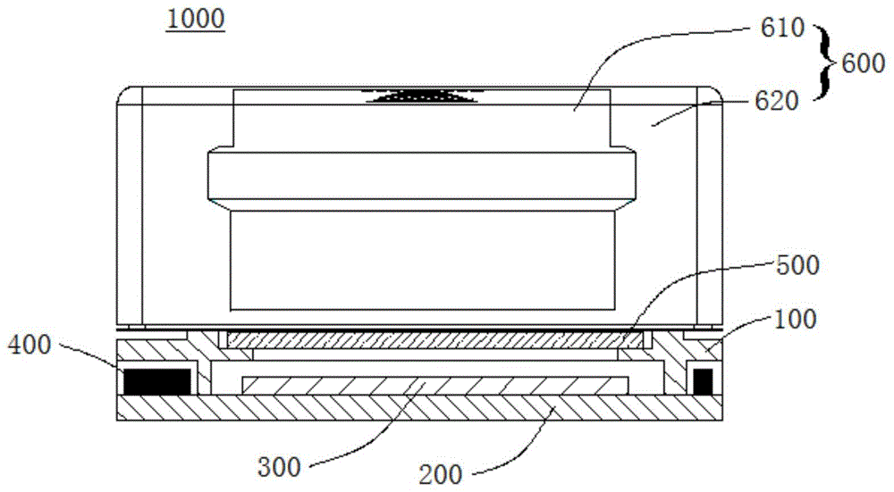
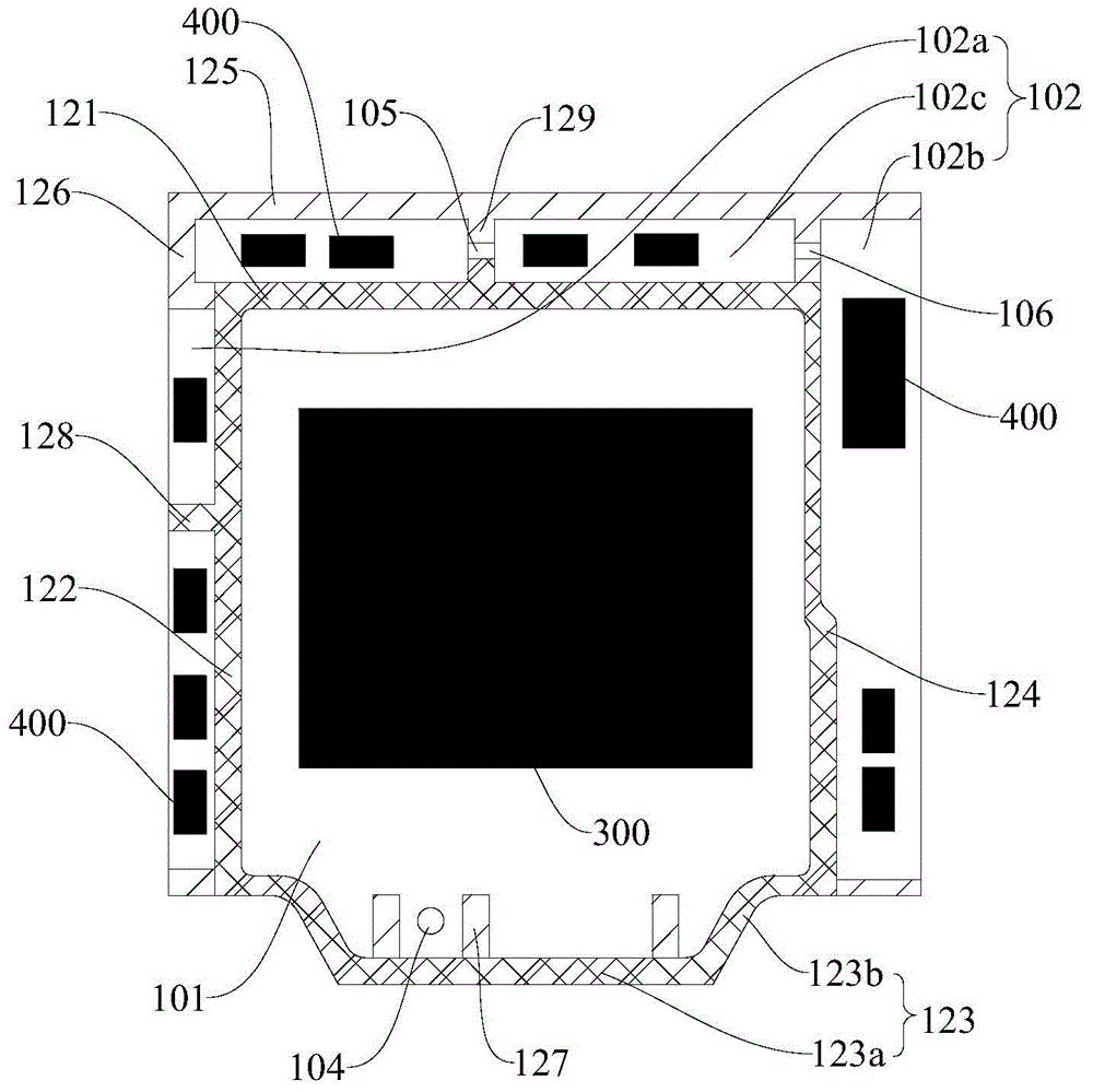
[0002] The image sensor chip and electronic components in the traditional camera module are all arranged on the circuit board and accommodated in the inner cavity of the camera module bracket. Since the electronic components are arranged around the image sensor chip, glue is drawn on the production line. When the rubber needle hits the electronic components, there will be a risk of hitting the electronic components. Once it hits the electronic components, a lot of debris will be generated, which is difficult to eliminate and will affect the image quality in severe cases.
Moreover, particles and impurities are easy to hide between the electronic components and the capacitive conductive sheet on the circuit board. When the camera is shaken, the particles and impurities may fall into the image sensing area of ​​the image sensor chip and seriously affect the imaging effect.

Method used


Image

  • Camera module set support and camera module set with same
  • Camera module set support and camera module set with same
  • Camera module set support and camera module set with same

Examples


Embodiment Construction

[0039] Embodiments of the present invention are described in detail below, examples of which are shown in the drawings, wherein the same or similar reference numerals designate the same or similar elements or elements having the same or similar functions throughout. The embodiments described below by referring to the figures are exemplary and are intended to explain the present invention and should not be construed as limiting the present invention.

[0040] In describing the present invention, it should be understood that the terms "center", "longitudinal", "transverse", "length", "width", "thickness", "upper", "lower", "front", " Back", "Left", "Right", "Vertical", "Horizontal", "Top", "Bottom", "Inner", "Outer", "Clockwise", "Counterclockwise", "Axial", The orientation or positional relationship indicated by "radial", "circumferential", etc. is based on the orientation or positional relationship shown in the drawings, and is only for the convenience of describing the presen...


PUM


Abstract

The invention discloses a camera module set support and a camera module set with the same. The camera module set support comprises a support body and a side wall portion; a through hole which passes through the support body along the thickness direction of the support body is formed in the support body; the side wall portion is arranged on the support body and is ring-shaped and surrounds the through hole; an inner mounting space and an external mounting space are defined between the support body and the side wall portion, wherein the inner mounting space is located at the inner side of the side wall part and is communicated with the through hole and is used for mounting an image sensing chip, and the external mounting space is located at the outer side of the side wall portion and is used for mounting an electronic element. The camera module set support of the invention has the inner mounting space and the external mounting space, and the image sensing chip is mounted in the inner mounting space, and the electronic element is mounted in the external mounting space, and therefore, influence on imaging which is caused by a situation in which dust and debris enter an image sensing region of the image sensing chip can be eliminated.

Description

technical field [0001] The invention relates to the field of imaging technology, in particular to a camera module bracket and a camera module with the same. Background technique [0002] The image sensor chip and electronic components in the traditional camera module are all arranged on the circuit board and accommodated in the inner cavity of the camera module bracket. Since the electronic components are arranged around the image sensor chip, glue is drawn on the production line. When the rubber needle hits the electronic components, there will be a risk of hitting the electronic components. Once it hits the electronic components, a lot of debris will be generated, which is difficult to eliminate and will affect the image quality in severe cases. Moreover, particles and impurities are easily hidden between the electronic components and the capacitive conductive sheet on the circuit board. When the camera is shaken, the particles and impurities may fall into the image sensin...

Claims


Application Information

Patent Timeline
IPC IPC(8): H04N5/225G03B17/56G03B17/02
Inventor 李巍于立新
Owner NANCHANG OFILM HUAGUANG TECH CO LTD
Learn More