Brake device of track conveying equipment

A brake device and rail transportation technology, which is applied in the direction of transportation and packaging, brakes interacting with brake components and rails, railway braking systems, etc., can solve the problems of inconvenient installation of disc spring replacement, worn brake blocks, and installation accuracy Advanced problems, to achieve the effect of good braking effect, fast braking speed and large opening angle

Active Publication Date: 2015-09-23
XIANGTAN HENGXIN IND
View PDF5 Cites 7 Cited by
  • Summary
  • Abstract
  • Description
  • Claims
  • Application Information

AI Technical Summary

Problems solved by technology

[0002] The brake of the rail transport vehicle is an essential device to ensure safe operation. The existing brakes include two types. One is that the brake hook is hinged on the piston rod or the movable push rod through the middle hole to form a caliper brake hook. The two-sided brake is clamped on both sides of the track. This kind of brake hook can be opened to the two outer sides and lifted above the track surface. It is suitable for ordinary tracks and can pass through track switches, but it also has high installation accuracy. When the brake car deviates too much from the track, the brake hook cannot grasp the track or cannot grasp the track surface in a wide range when the brake car is braking, and the brake failure or insufficient braking occurs. One is the immediate Type brake, its structure is designed to be equipped with a friction block at the bottom of the lower piston rod, the lower part of the lower piston rod is in the shape of a step with decreasing diameter, and brake hooks are installed on both sides of the step of the lower piston rod. Move directly to the top surface of the track, and the brake hook rotates downward around the limit shaft due to the gradually larger contact diameter of the lower piston rod to clamp the two sides of the track, forming a three-sided braking braking method. The braking force is greater, but there are also some shortcomings. The brake hook of this kind of brake can only open a small limited distance to both sides of the track, cannot be lifted above the track surface, and cannot pass through the track switch. At the same time, it must ensure that the brake is installed Right above the track, if the brake car deviates, one side of the brake car may touch the side of the track when the brake car is in normal working condition, resulting in braking in a state that should not be braked and affecting the normal operation of the brake car, or serious worn brake pads
The brakes of the above two methods all adopt the one-piece assembly method in which the disc spring is built into the brake cylinder, which is inconvenient for installation, maintenance and replacement of the disc spring.

Method used


Image

  • Brake device of track conveying equipment
  • Brake device of track conveying equipment
  • Brake device of track conveying equipment

Examples


Embodiment Construction

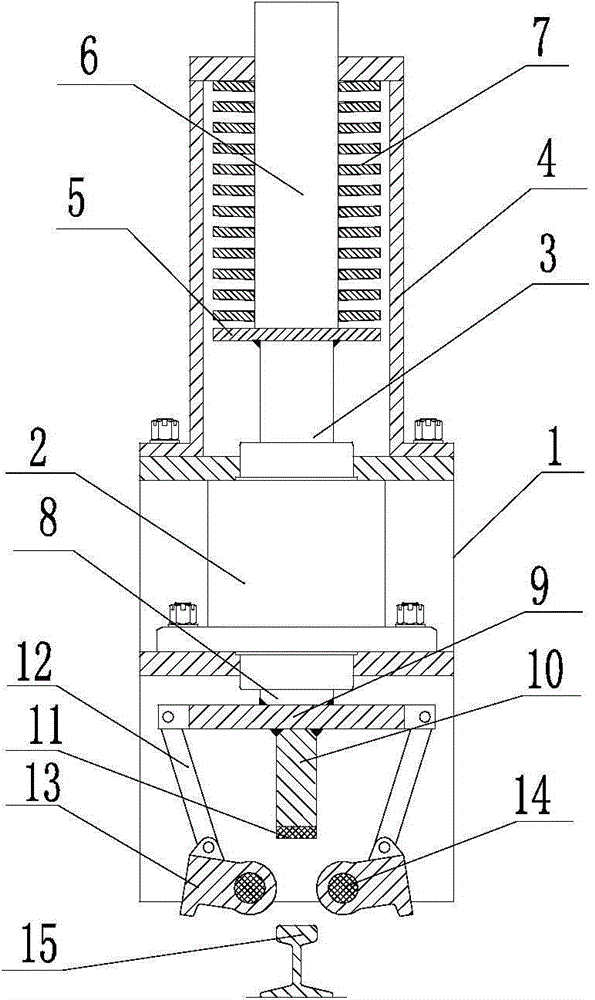
[0018] Such as figure 1 , figure 2 As shown, a brake device for rail transportation equipment is equipped with an oil cylinder 2 on the bracket 1, a lower push rod 8 and an upper push rod 3 are respectively installed on both sides of the oil cylinder 2, and a guide rod frame is installed on the upper side of the oil cylinder 2. 4. A spring push plate 5 is installed on the upper push rod 3, and a spring 7 is installed between the spring push plate 5 and the guide rod frame 4. The spring 7 is a disc spring; 9 The lower side is equipped with a brake lever 10, and a connecting rod 12 is installed on the top of the pressure plate 9. The other end of the connecting rod 12 is connected to the rotating brake claw 13, and the rotating brake claw 13 passes through the rotation axis of the rotating brake claw. 14 is contained on the support 1.

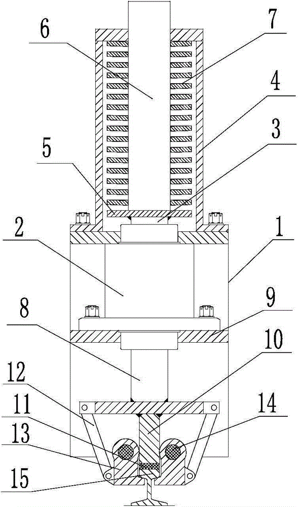
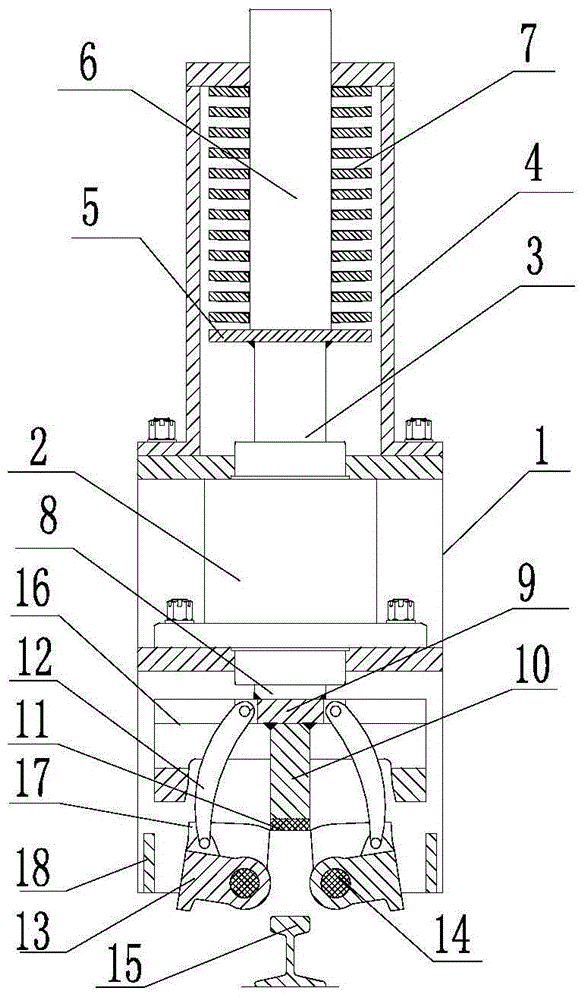
[0019] Such as image 3 , Figure 4 , Figure 5 , Figure 6 , Figure 7 , Figure 8 As shown, a brake device for rail transportation eq...


PUM


Abstract

The invention discloses a brake device of track conveying equipment. An oil cylinder is installed on a supporting frame. A lower push rod and an upper push rod are installed on two sides of the oil cylinder respectively. A guide rod frame is installed on the upper side of the oil cylinder. A spring push plate is installed on the upper push rod, and a spring is installed between the spring push plate and the guide rod frame. A press plate is installed at one end of the lower push rod. A brake rod is installed on the lower side of the press plate. A connecting rod is installed on the upper side of the press plate, and the other end of the connecting rod is connected with a rotary brake claw. The rotary brake claw is installed on the supporting frame through a rotary shaft of the rotary brake claw. The brake device of the track conveying equipment has the technical benefits that 1, the top surface and two lateral surfaces of a track can be braked simultaneously, the brake speed is high, and the brake effect is good; the rotary brake claw can hook the track, prevent a track conveying brake vehicle from disengaging from the track and prevent the brake vehicle from overturning; 2, the brake vehicle is not affected when passing through a track turnout; 3, the brake device is convenient to install and maintain.

Description

technical field [0001] The invention relates to a braking device for rail transportation equipment Background technique [0002] The brake of the rail transport vehicle is an essential device to ensure safe operation. The existing brakes include two types. One is that the brake hook is hinged on the piston rod or the movable push rod through the middle hole to form a caliper brake hook. The two-sided brake is clamped on both sides of the track. This kind of brake hook can be opened to the two outer sides and lifted above the track surface. It is suitable for ordinary tracks and can pass through track switches, but it also has high installation accuracy. When the brake car deviates too much from the track, the brake hook cannot grasp the track or cannot grasp the track surface in a wide range when the brake car is braking, and the brake failure or insufficient braking occurs. One is the immediate Type brake, its structure is designed to be equipped with a friction block at t...

Claims


Application Information

Patent Timeline
Patent Type & Authority Applications(China)
IPC IPC(8): B61H7/12
CPCB61H7/12
Inventor 肖公平肖连平林春年
Owner XIANGTAN HENGXIN IND
Why Eureka
Try Eureka