A Redundant Electronically Controlled Interlocking System for Mechanically Interlocked Dampers

A mechanical and damper technology, which is applied in mine/tunnel ventilation, mining equipment, earthwork drilling and mining, etc., can solve the problems of hindering the movement of gears in the transmission chain and interlock box, high cost of electronic devices, and restrictions on popularization and application. Achieve the effects of avoiding potential safety hazards, improving monitoring accuracy, and improving safety performance

Active Publication Date: 2018-01-23
怀远县翰邦科技咨询有限公司
View PDF5 Cites 0 Cited by
  • Summary
  • Abstract
  • Description
  • Claims
  • Application Information

AI Technical Summary

Problems solved by technology

[0003] There are many forms of air door interlock, the common ones are mechanical and electronic. The mechanical interlock is usually to install an interlock box between two air doors, and the two air doors are respectively connected to the interlock box through a transmission chain. When one of the air doors When the damper is opened, the transmission chain drives the interlock box to lock the other damper. This interlocking method is purely mechanically driven, with a simple structure and low cost. It is the most common damper interlock structure in underground coal mines at present. , a large amount of dust often hinders the movement of the transmission chain and the gears in the interlock box, causing the interlock to fail, causing a large number of accidents, and seriously endangering the safety of the underground; The sensor is installed to detect the action of the electric switch. When one of the air doors is open, the electric switch of the other air door is locked through remote communication, so as to realize the interlock of the air door. The electronic interlock method responds quickly. There are fewer components, and the failure rate of the components is low, but its interlocking depends on the remote communication of the electric switch on the two dampers. When an abnormal situation occurs underground and affects the communication, it is easy to cause misoperation and affect the safety of the damper. At the same time, the electronic device The cost is relatively high. When the mechanical interlocking transformation is required, it needs to be replaced as a whole, which costs a lot. In the case that most dampers are mechanical interlocking structures, their popularization and application are greatly restricted.

Method used


Image

  • A Redundant Electronically Controlled Interlocking System for Mechanically Interlocked Dampers

Examples


Embodiment Construction

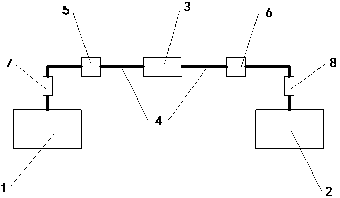
[0014] See attached figure 1 , which describes a preferred embodiment of the electronically controlled interlocking system according to the present invention. A redundant electronic control interlock system for mechanical interlock dampers, wherein the mechanical interlock dampers are common two-sided dampers, including A door and B door, and A and B doors are connected with a transmission chain. There is an interlock box in the middle of the transmission chain, and the transmission chain is a chain structure. When the damper moves, the gears on its rotating parts drive the chain to move, driving the relevant gears in the interlock box to rotate, thereby locking the transmission on the other side. chain, which in turn prevents movement of the damper on the other side. The above-mentioned interlocking structure and method are well-known technologies in the art, and will not be repeated here.

[0015] In order to better realize the interlocking of the air door and increase the...


PUM


Abstract

A redundant electronically controlled interlock system for mechanical interlock dampers. The mechanical interlock dampers include door A, door B, transmission chain and interlock box. The transmission chain is connected to door A and door B respectively. The transmission chain There is an interlock box in the middle, a first sensor part and a first locking part are arranged on the side of the transmission chain near door A, a second sensor part and a second locking part are arranged on the side of the transmission chain near door B, and the first sensor part is electrically connected. The first locking component is connected, the second sensor component is electrically connected to the second locking component, and the first sensor component and the second sensor component are electrically connected to each other. The invention has quick response, high reliability, and improves the overall safety performance; without any modification to the damper, the potential safety hazard caused by the modification of the damper is avoided, the monitoring accuracy is high, and the failure of the transmission chain can be detected early; the required parts are few , low price, small transformation cost, suitable for large-scale promotion in coal mines.

Description

technical field [0001] The invention relates to an interlocking system of a damper, in particular to an electronically controlled interlocking system for a mechanically interlocked damper with a transmission chain. Background technique [0002] In the coal mine production process, in order to ensure the safety of underground ventilation and the needs of production and transportation, dampers must be installed in some roadways to isolate areas with different wind pressures. Usually dampers are installed in pairs, including door A and door B. When people pass through and transport, such as entering the area outside door B from the area outside door A, door A must be opened first, and door B must not be opened at this time. , when a person or vehicle enters the area between the two air doors, door A is closed, and door B can be opened at this time, and the isolation and communication of the area is realized through this interlocking control method. [0003] There are many form...

Claims


Application Information

Patent Timeline
Patent Type & Authority Patents(China)
IPC IPC(8): E21F1/10
Inventor 苏琳
Owner 怀远县翰邦科技咨询有限公司
Why Eureka
Try Eureka