Air conditioner mounting rack
A mounting frame and air-conditioning technology, which is applied in the field of mounting frames, can solve the problems of poor working conditions, high labor intensity and danger, and troublesome installation, disassembly and moving of installers, and achieve the effects of low cost, simple structure, and reduced risk
- Summary
- Abstract
- Description
- Claims
- Application Information
AI Technical Summary
Problems solved by technology
Method used
Image

Examples
Embodiment Construction
[0027] The present invention will be further described below in conjunction with accompanying drawing.
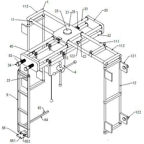
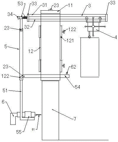
[0028] As shown in the figure, the air conditioner installation frame includes a fixed frame 1 , a movable plate 2 , a hanger 3 , a lifting device 4 , and a pressing arm 5 .
[0029] 1. Fixed frame.
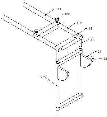
[0030] Such as figure 1 As shown, taking the frame of the double-tube structure as an example, the fixed frame 1 is in the shape of "Π" when it is opened, and the horizontal frame 11 is a telescopic double-tube frame, and its structure is that the two ends of the parallel double outer tubes 111 are fixedly connected to the connecting rods 113, One end of the double nozzle is inserted into the corresponding parallel double inner pipe 112, the other end of the inner pipe is fixedly connected to the connecting rod 113, the mullion 12 is fixedly connected to the connecting rod 113 between the parallel double vertical pipes, and the two sides of the frame are fixedly connected wit...
PUM
 Abstract
Description
Claims
Application Information