Sensor probe for measuring electrical parameters of underground rock

A technology of sensor probes and electrical parameters, applied in the direction of measuring electricity, measuring devices, measuring electrical variables, etc., can solve the problem that the resistivity and dielectric constant of rock core samples cannot be obtained in real time, the electrical parameters of rocks cannot be measured, and the electrical parameters are not sensitive to changes And other issues

Inactive Publication Date: 2015-09-23
UNIV OF ELECTRONICS SCI & TECH OF CHINA
View PDF9 Cites 0 Cited by
  • Summary
  • Abstract
  • Description
  • Claims
  • Application Information

AI Technical Summary

Problems solved by technology

Because the traditional measurement method needs to take out the core from the downhole and send it back to the laboratory, this process leads to a long measurement cycle and high cost, and it is impossible to obtain the resistivity and dielectric constant of the core sample in real time
[0002] The downhole measurement of core samples can obtain formation core information in real time, but the downhole environment is different from the laboratory measurement environment, and the measurement will be affected by many factors. First, the downhole is full of conductive mud solution. At this time Since the resistivity of the rock is much higher than that of the mud, the conduction current flowing from the emitter electrode will directly pass through the conductive mud to reach the collector electrode, and very little current can penetrate the mud and enter the rock, which will inevitably lead to the failure of the probe to measure the rock. Electrical parameters
[0003] Since the conductive mud will block the current flowing from the electrode into the high-resistance rock, it will not be sensitive to the change of the electrical parameters of the rock.

Method used


Image

  • Sensor probe for measuring electrical parameters of underground rock
  • Sensor probe for measuring electrical parameters of underground rock
  • Sensor probe for measuring electrical parameters of underground rock

Examples


Embodiment Construction

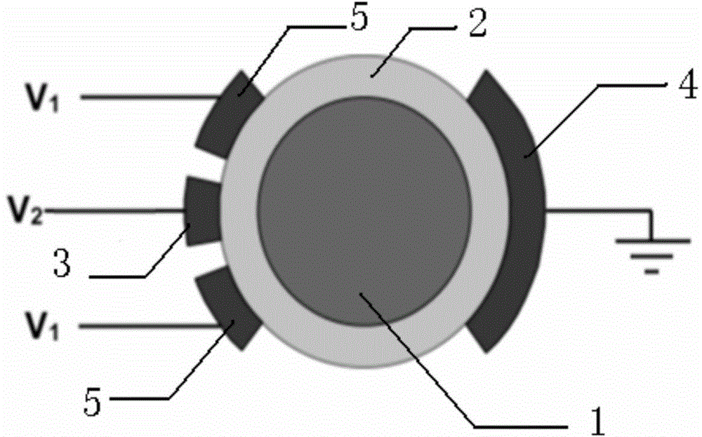
[0012] The present invention adopts specific measures to guide the current to penetrate the conductive mud and enter the inside of the rock, so as to collect and bring out the electrical parameters inside the rock.

[0013] While supplying power to the emitter electrode, by applying an appropriate voltage to the shield electrode, the surrounding of the internal electrode is relatively high potential, so that the current flowing from the emitter electrode cannot be conducted along the conductive mud. Selecting the appropriate voltage and electrode form can make The current penetrates the conductive mud, into the interior of the rock, and through the rock to the grounded plate.

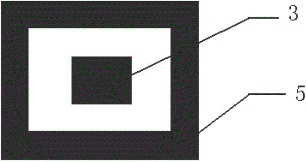
[0014] Such as figure 1 As shown, the sensor probe of the present invention is used to measure the electrical parameters of the sampled rock 1 . Rock 1 is wrapped by conductive mud 2 . The sensor probe of the present invention comprises a transmitter electrode 3, a collector electrode 4, a transmitter...


PUM


Abstract

The invention provides a sensor probe for measuring electrical parameters of an underground rock. The sensor probe comprises an emitter electrode, a collector electrode and a voltage source of the emitter electrode, and the voltage source of the emitter electrode is connected with the collector electrode and the emitter electrode via leads. The sensor probe is characterized by also comprising a shielding electrode and a voltage source of the shielding electrode, the shielding electrode is annular, the emitter electrode is arranged in a ring of the shielding electrode, and the voltage source of the shielding electrode is connected with the collector electrode and the shielding electrode via leads. The emitter electrode and the collector electrode are respectively arranged at the two sides of the sampled underground rock opposite to each other, the voltage source of the shielding electrode is loaded on the shielding electrode, and thus, current flowing out of the emitter electrode can penetrate a conductive slurry in parallel and reaches the collector electrode in the rock. The sensor probe can measure underground core samples in real time, and accurately and effectively obtains core information of the stratum in real time.

Description

Background technique [0001] Core electrical parameters are very important for correcting logging curves. The traditional method of measuring core electrical parameters needs to collect core samples and send them back to the ground laboratory for measurement. The sensor probe used in the measurement includes the emitter electrode and the collector electrode. The emitter electrode and the collector electrode are connected through a voltage source. The current flowing from the emitter electrode passes through the rock to the collector electrode. When the current passes through the rock, it will be affected by the rock resistivity and dielectric constant. Therefore, the circuit impedance will change. By establishing the relationship between the circuit impedance and the rock resistivity and permittivity, the resistivity and permittivity of the rock core to be tested can be deduced according to the measured impedance value. Because the traditional measurement method needs to take o...

Claims


Application Information

Patent Timeline
Patent Type & Authority Applications(China)
IPC IPC(8): G01R31/00
Inventor 孙向阳付海博聂在平
Owner UNIV OF ELECTRONICS SCI & TECH OF CHINA
Why Eureka
Try Eureka