Mechanism for debugging number of revolutions of motor rotation

A technology of rotation speed and rotation rod, which is applied in the field of motor rotation speed debugging mechanism, and can solve the problems of inconvenient detection of motor rotation stability and complex structure

Inactive Publication Date: 2015-09-23
胡和萍
View PDF8 Cites 2 Cited by
  • Summary
  • Abstract
  • Description
  • Claims
  • Application Information

AI Technical Summary

Problems solved by technology

The existing motor rotation stability detection device has a complex s

Method used


Image

  • Mechanism for debugging number of revolutions of motor rotation
  • Mechanism for debugging number of revolutions of motor rotation

Examples


Embodiment Construction

[0012] The preferred embodiments of the present invention will be described in detail below in conjunction with the accompanying drawings, so that the advantages and features of the present invention can be more easily understood by those skilled in the art, so as to define the protection scope of the present invention more clearly.

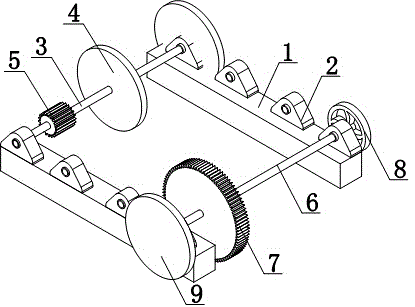
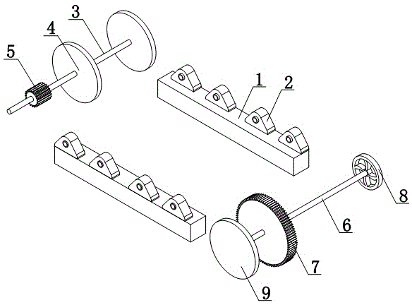
[0013] Such as figure 1 and figure 2 As shown, a motor rotation speed adjustment mechanism includes two parallel support bars 1, and a number of blocks 2 are arranged on the support bar 1, and a first rotating rod 3 is arranged between a pair of blocks 2, and a first rotating rod 3 is provided between the pair of blocks 2 A rotating rod 3 is set with a first rotating wheel 4 and a threaded pipe 5; a second rotating rod 6 is set between the other pair of blocks 2, and a gear 7 is set on the second rotating rod 6; the second rotating rod 6 is set with The hand wheel 8 and the second rotating rod 6 are sleeved with a rotating ring 9.

[0014] The...


PUM


Abstract

The invention discloses a mechanism for debugging the number of revolutions of motor rotation, which comprises two parallelly arranged supporting bars and is characterized in that each supporting bar is provided with a plurality of clamping blocks, a first rotating rod is arranged between a pair of clamping blocks, and the first rotating rod is provided with a first rotating wheel and a threaded tube in a sleeved mode; a second rotating rod is arranged between another pair of clamping blocks, and the second rotating rod is provided with a gear in a sleeved mode. According to the mechanism disclosed by the invention, a driving motor connected to a driving gear can be butted with the threaded tube, thereby being capable of controlling rotation of the first rotating rod, and thus further being capable of controlling rotation of the first rotating wheel. The rotational stability of the motor can be known through the rotational stability of the first rotating wheel.

Description

technical field [0001] The invention relates to a debugging mechanism, in particular to a motor rotation speed debugging mechanism. Background technique [0002] The main function of the motor is to generate driving torque as a power source for electrical appliances or various machines. Its main function is to convert mechanical energy into electrical energy. At present, the most commonly used is to use heat energy, water energy, etc. to drive the rotor of the generator to generate electricity. The existing motor rotation stability detection device has a complicated structure, and it is inconvenient to detect the motor rotation stability. Contents of the invention [0003] The present invention mainly solves the technical problems existing in the prior art, thereby providing a driving motor connected with a driving gear and a threaded pipe, so that the rotation of the first rotating rod can be controlled, and the rotation of the first rotating wheel can also be controlled...

Claims


Application Information

Patent Timeline
IPC IPC(8): G01R31/34
Inventor 胡和萍
Owner 胡和萍
Why Eureka
Try Eureka