liquid storage tank

A liquid storage tank and liquid storage technology, applied in the direction of hydraulic brake transmission device, fluid pressure actuation device, oil supply tank device, etc., can solve the problem of difficult capture

Active Publication Date: 2019-11-01
AUTOLIV NISSIN BRAKE SYST JAPAN CO LTD
View PDF5 Cites 0 Cited by
  • Summary
  • Abstract
  • Description
  • Claims
  • Application Information

AI Technical Summary

Problems solved by technology

However, in this liquid storage tank, if foreign matter such as dust gets mixed into the tank during maintenance such as filter exchange, it is difficult to capture it.

Method used


Image

  • liquid storage tank
  • liquid storage tank
  • liquid storage tank

Examples


no. 1 approach

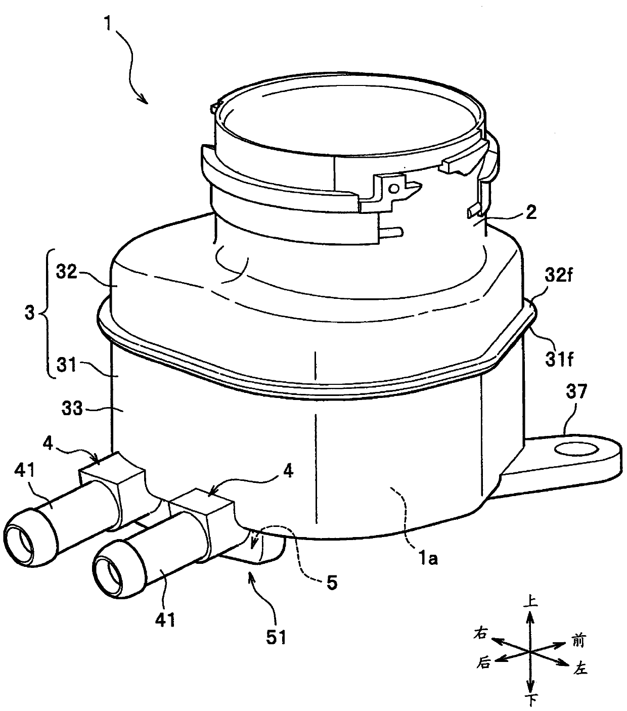
[0049] like figure 1 As shown, the reservoir tank 1 of this embodiment is held by an unillustrated bracket of the vehicle. For example, the bracket is supported by a side wall of the engine room or the like under a hood in the engine room (not shown). In addition, although the reservoir tank connected to the master cylinder device provided in the hydraulic pressure control device was exemplified below, the device to which the reservoir tank is connected is not limited.

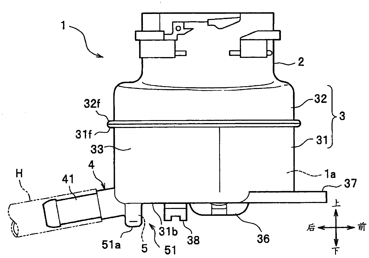
[0050] For example, the master cylinder device is attached to the dash panel that divides the engine room and the vehicle interior. The working fluid (brake fluid) stored in the reservoir tank 1 passes through the connecting hose H (refer to figure 2 hereinafter the same) are supplied to the master cylinder device.

[0051] In addition, in the engine room, an engine, a transmission, and the like, which are not shown in the figure, or peripheral devices thereof, or an electric motor instead of the engine, a...

no. 2 approach

[0085] refer to Figure 11 The liquid storage tank 1 of the second embodiment will be described. This embodiment differs from the above-described first embodiment in that a concave portion 60 is provided opposite to the working fluid supply port 4B provided on the bottom wall 31c of the lower half body 31 . In addition, a hose joint portion is integrally provided with the hydraulic fluid supply port 4B.

[0086] like Figure 11 As shown in (a), the concave portion 60 is opened and formed in a cylindrical shape so as to surround the opening portion 4a of the working fluid supply port 4B provided on the bottom surface 31a in plan view. On the inner peripheral surface 2a ( Figure 11 In (a) shown by a two-dot chain line) projected onto the bottom surface 31a, the concave portion 60 is arranged between the working fluid inlet 2 (inner peripheral surface 2a) and the working fluid supply port 4B (opening 4a). Formed space S1.

[0087] like Figure 11 As shown in (b), the conca...


PUM


Abstract

A liquid storage tank (1) capable of properly capturing foreign matter mixed into the tank. The liquid storage tank (1) includes: a liquid storage body (3) forming a working fluid storage chamber (1a) inside, a working fluid injection port (2) provided on the upper part of the liquid storage body (3), a The working fluid supply port (4) at the lower part of the accumulator main body (3) is configured such that a groove-like recess (5) is formed on the bottom surface (31a) of the accumulator main body (3), and the working When the liquid inlet (2) is projected on the bottom surface (31a) side of the accumulator body (3), the concave portion (5) is arranged between the working fluid inlet (2) and the working fluid supply port (4).

Description

technical field [0001] The invention relates to a liquid storage tank. Background technique [0002] Conventionally, as a fluid reservoir, it is known to be used in a master cylinder device for a vehicle or a hydraulic pressure control device for a vehicle (for example, refer to Patent Document 1). [0003] The reservoir tank is configured as a separate tank separate from the master cylinder device, and is configured to supply hydraulic fluid to the master cylinder device through a connecting hose or the like. [0004] Patent Document 1: (Japanese) Unexamined Patent Application Publication No. 2004-106778 [0005] In the liquid storage tank of Patent Document 1, a filter is attached to the injection port of the working fluid. However, in this fluid storage tank, if foreign matter such as dust gets mixed into the tank during maintenance such as filter exchange, it is difficult to capture it. Contents of the invention [0006] An object of the present invention is to prov...

Claims


Application Information

Patent Timeline
Patent Type & Authority Patents(China)
IPC IPC(8): B60T11/26
CPCB60T11/26F15B1/26F15B2201/413
Inventor 小堀哲生中村元泰
Owner AUTOLIV NISSIN BRAKE SYST JAPAN CO LTD
Why Eureka
Try Eureka