Exhaust gas treatment device
An exhaust gas treatment device and exhaust gas technology, which are applied in exhaust gas devices, combustion product treatment, climate sustainability, etc., can solve the problems of metal mesh breakage, breakage, mesh blockage of metal mesh, etc., and achieve the effect of damage suppression
- Summary
- Abstract
- Description
- Claims
- Application Information
AI Technical Summary
Problems solved by technology
Method used
Image
Examples
Embodiment 1
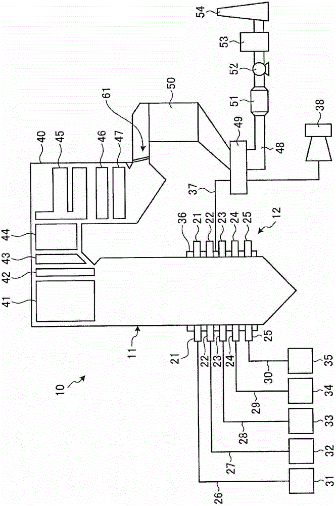
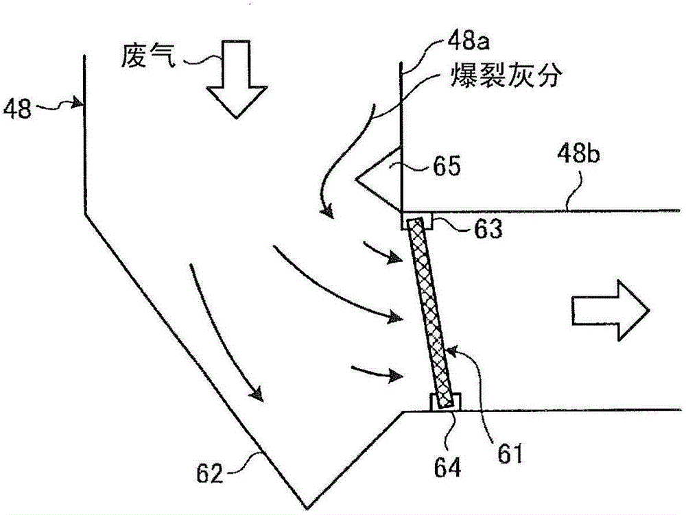
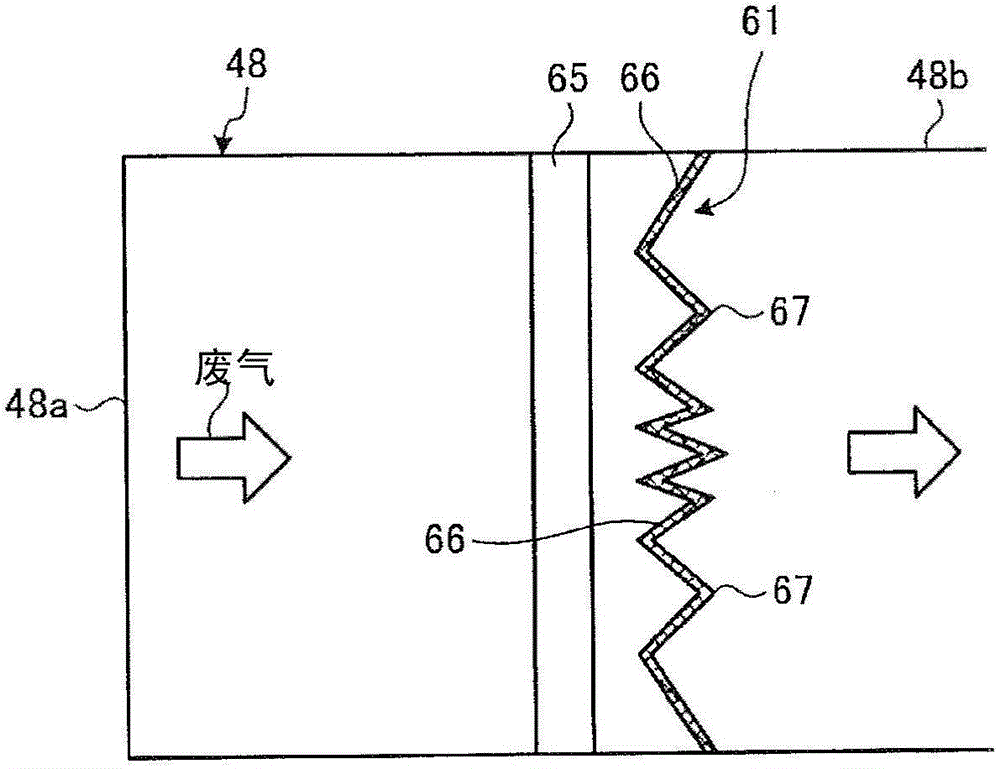
[0045] figure 1 is a schematic structural diagram showing a pulverized coal incineration boiler to which the exhaust gas treatment device according to Example 1 of the present invention is applied, figure 2 is a schematic side view showing the exhaust gas treatment device of Example 1, image 3 is a schematic plan view showing the exhaust gas treatment device of Example 1, Figure 4 It is a schematic diagram showing the pop-up ash collection part of Example 1.
[0046] The pulverized coal incineration boiler to which the exhaust gas treatment device of Example 1 is applied uses pulverized coal pulverized coal as a solid fuel, and burns the pulverized coal in a combustion furnace to recover heat generated by the combustion.
[0047] In this Example 1, as figure 1 As shown, the pulverized coal incineration boiler 10 is a traditional boiler with a furnace 11 and a combustion device 12 . The melting furnace 11 has a hollow shape of a square tube and is installed along the ver...
Embodiment 2
[0078] Figure 5 It is a front view of the explosion ash collection unit in the exhaust gas treatment device according to Example 2 of the present invention, Figure 6 It is a plan view of the pop-up ash collection part of Example 2, Figure 7 It is a side view of the pop ash collection part of Example 2.
[0079] In Embodiment 2, the basic structure of the exhaust gas treatment device is the same as that of Embodiment 1, only the structure of the explosion ash collection part is different. Such as Figure 5 ~ Figure 7 As shown, the explosion ash collection part 71 has a plurality of inclined parts inclined at a predetermined inclination angle with respect to the flow direction of the exhaust gas. The inclination angle of the inclined portion is small.
[0080] The explosion ash collection unit 71 has a plurality of (six in Example 2) inclined collection surfaces 72 (72a, 72b) that intersect with the exhaust gas flow direction and follow the vertical direction as the plura...
Embodiment 3
[0093] Figure 8 It is a front view of the explosion ash collection part in the exhaust gas processing apparatus which concerns on Example 3 of this invention. Figure 9 It is a side view of the pop ash collection part of Example 3.
[0094] In Embodiment 3, the basic structure of the exhaust gas treatment device is the same as that of Embodiments 1 and 2, only the structure of the explosion ash collection part is different. Such as Figure 8 and Figure 9 As shown, the explosion ash collection part 81 has a plurality of inclined parts inclined at a predetermined inclination angle with respect to the flow direction of the exhaust gas, and the inclination angle of the inclined part arranged in the central part of the exhaust gas pipe is set to be lower than that arranged in the outer peripheral part. The inclination angle of the inclined portion is small.
[0095] The explosion ash collection part 81 has a plurality of inclined collection surfaces 82 (82a, 82b) which inters...
PUM
 Abstract
Description
Claims
Application Information
 - R&D Engineer
- R&D Manager
- IP Professional
- Industry Leading Data Capabilities
- Powerful AI technology
- Patent DNA Extraction
Browse by: Latest US Patents, China's latest patents, Technical Efficacy Thesaurus, Application Domain, Technology Topic, Popular Technical Reports.
© 2024 PatSnap. All rights reserved.Legal|Privacy policy|Modern Slavery Act Transparency Statement|Sitemap|About US| Contact US: help@patsnap.com


