Exhaust gas treatment device

A waste gas treatment device and technology for waste gas, which are applied in combination devices, lighting and heating equipment, and dispersed particle separation, etc., can solve the problems of mesh blockage, wire mesh damage, and abrasion of wire mesh, and achieve the effect of damage suppression.

Inactive Publication Date: 2016-01-20
MITSUBISHI POWER LTD
View PDF9 Cites 0 Cited by
  • Summary
  • Abstract
  • Description
  • Claims
  • Application Information

AI Technical Summary

Problems solved by technology

Therefore, large pieces of explosion ash collide with the wire mesh or the like, and there is a problem that the mesh of the wire mesh is locally clogged or worn, or the wire mesh is damaged.

Method used


Image

  • Exhaust gas treatment device
  • Exhaust gas treatment device
  • Exhaust gas treatment device

Examples


Embodiment 1

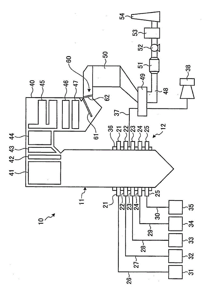
[0071] figure 1 is a schematic configuration diagram showing a pulverized coal incineration boiler to which the exhaust gas treatment device according to Example 1 of the present invention is applied, figure 2 is a schematic side view showing the exhaust gas treatment device of Example 1, image 3 It is a schematic plan view showing the exhaust gas treatment device of Example 1.

[0072] The pulverized coal incineration boiler to which the exhaust gas treatment device of Example 1 is applied is a boiler that can use pulverized coal after pulverizing coal as a solid fuel, burn the pulverized coal with a combustion furnace, and treat Heat is recovered.

[0073] In this embodiment 1, if figure 1 As shown, the pulverized coal incineration boiler 10 is a traditional boiler with a furnace 11 and a combustion device 12 . The melting furnace 11 has a square tube hollow shape and is installed along the vertical direction, and a combustion device 12 is provided at a lower portion o...

Embodiment 2

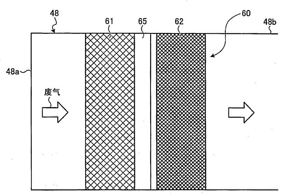
[0104] Figure 4 It is a schematic diagram showing the exhaust gas treatment device according to the second embodiment of the present invention. It should be noted that members having the same functions as those in the above-mentioned embodiments are denoted by the same reference numerals, and detailed description thereof will be omitted.

[0105] In the exhaust gas treatment device of embodiment 2, such as Figure 4As shown, an explosion ash collection part 60 capable of collecting the explosion ash in the exhaust gas is provided between the heat recovery part and the harmful substance removal part in the exhaust gas pipe 48. The explosion ash collection part 60 includes: The first trapping portion 61 with a low aperture ratio; the second trapping portion 62 with a low aperture ratio.

[0106] The exhaust gas pipe 48 is constituted by a first pipe 48a extending in the vertical direction and a second pipe 48b extending in the horizontal direction communicating in directions ...

Embodiment 3

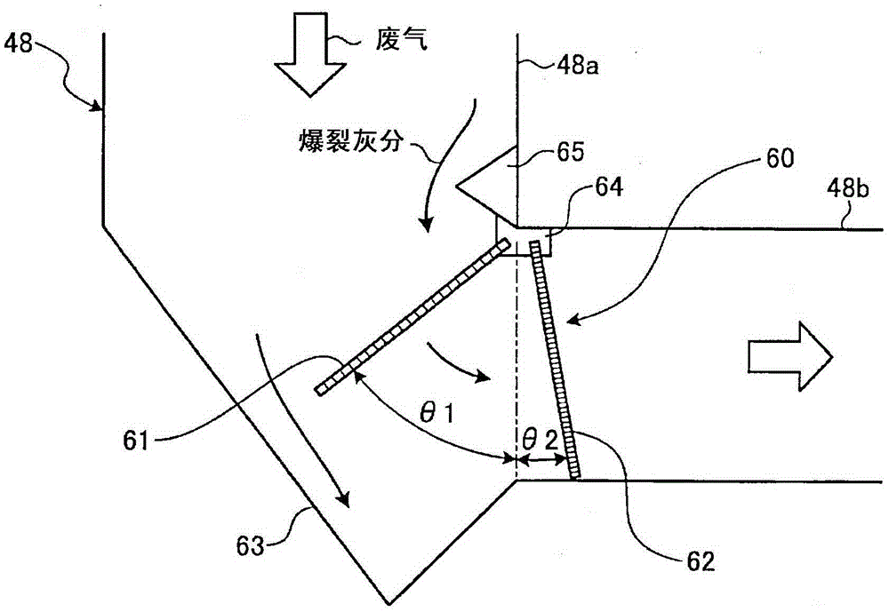
[0116] Figure 5 It is a schematic diagram showing the exhaust gas treatment device according to the third embodiment of the present invention. It should be noted that members having the same functions as those in the above-mentioned embodiments are denoted by the same reference numerals, and detailed description thereof will be omitted.

[0117] In the exhaust gas treatment device of embodiment 3, such as Figure 5 As shown, an explosion ash collection part 60 capable of collecting the explosion ash in the exhaust gas is provided between the heat recovery part and the harmful substance removal part in the exhaust gas pipe 48. The explosion ash collection part 60 includes: The first trapping portion 61 with a low aperture ratio; the second trapping portion 62 with a low aperture ratio. The upper end portion of the first collecting portion 61 is fixed to a bracket 64 fixed inside the corner of the communication portion between the first pipe 48a and the second pipe 48b, and t...


PUM


Abstract

An exhaust gas treatment device, wherein an exhaust gas pipe (48) through which combustion gas can flow, a heat recovery unit which is provided in the exhaust gas pipe (48) and can recover heat in exhaust gas, a toxic substance removal unit which is provided on the downstream side in the flow direction of the exhaust gas from the heat recovery unit in the exhaust gas pipe (48) and can remove toxic substances in the exhaust gas, and a popcorn ash trapping unit (60) which is provided between the heat recovery unit and the toxic substance removal unit in the exhaust gas pipe (48) and can trap popcorn ash in the exhaust gas are provided, and a first trapping part (61) having a high aperture ratio and a second trapping part (62) having a lower aperture ratio than the aperture ratio of the first trapping part (61) are provided as the popcorn ash trapping unit (60), thereby making it possible to appropriately trap the popcorn ash.

Description

technical field [0001] The present invention relates to an exhaust gas treatment device applied to boilers for generating steam in power generation, factories, and the like. Background technique [0002] For example, a conventional pulverized coal combustion boiler has a hollow furnace installed in the vertical direction, and a plurality of combustion furnaces are arranged in a circumferential direction on the furnace wall and arranged in multiple stages in the vertical direction. The combustion furnace is supplied with a mixed gas of pulverized coal (fuel) and primary air and high-temperature secondary air, and the mixed gas and secondary air are blown into the furnace to form a flame. Combustion takes place in the furnace. In addition, a flue is connected to the upper part of the furnace, and a superheater, a reheater, an economizer, etc. for recovering the heat of the exhaust gas are installed in the flue, and the waste gas generated by combustion in the furnace and wate...

Claims


Application Information

Patent Timeline
Patent Type & Authority Patents(China)
IPC IPC(8): F23J15/00B01D50/00F23J15/02
CPCF23J15/022F23J2217/20F23J2217/30
Inventor 冈元章泰户高心平小田学坂田展康河越博美
Owner MITSUBISHI POWER LTD
Why Eureka
Try Eureka