Method and switch for sending multicast message

A multicast message and switch technology, applied in the network field, can solve problems such as difficulty in supporting commercial chips

A multicast message and switch technology, applied in the network field, can solve problems such as difficulty in supporting commercial chips

CN104954265BActive Publication Date: 2018-06-15HUAWEI TECH CO LTD

Image

  • Method and switch for sending multicast message
  • Method and switch for sending multicast message
  • Method and switch for sending multicast message

Examples


Embodiment Construction

[0029] The present invention will be described in detail below in conjunction with the accompanying drawings and embodiments.

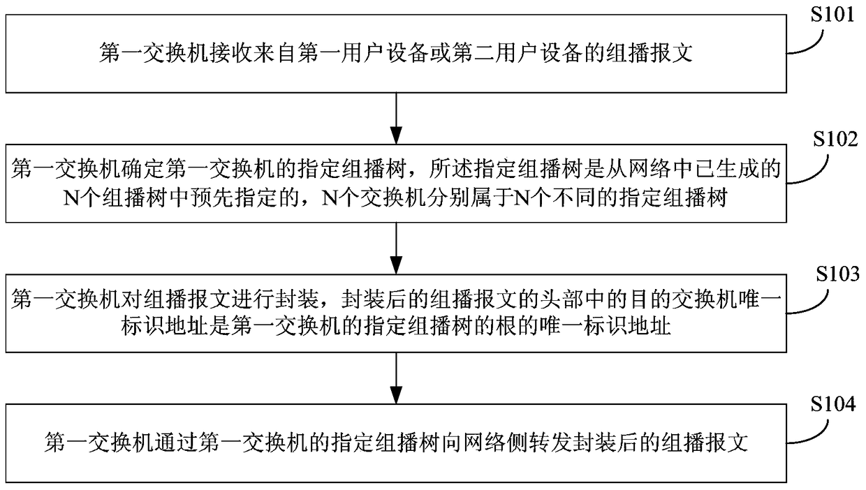
[0030] refer to figure 2 , figure 2 It is a flow chart of an embodiment of the method for sending a multicast message in the present invention, and this embodiment is a flow chart of the first switch encapsulating a message, including:

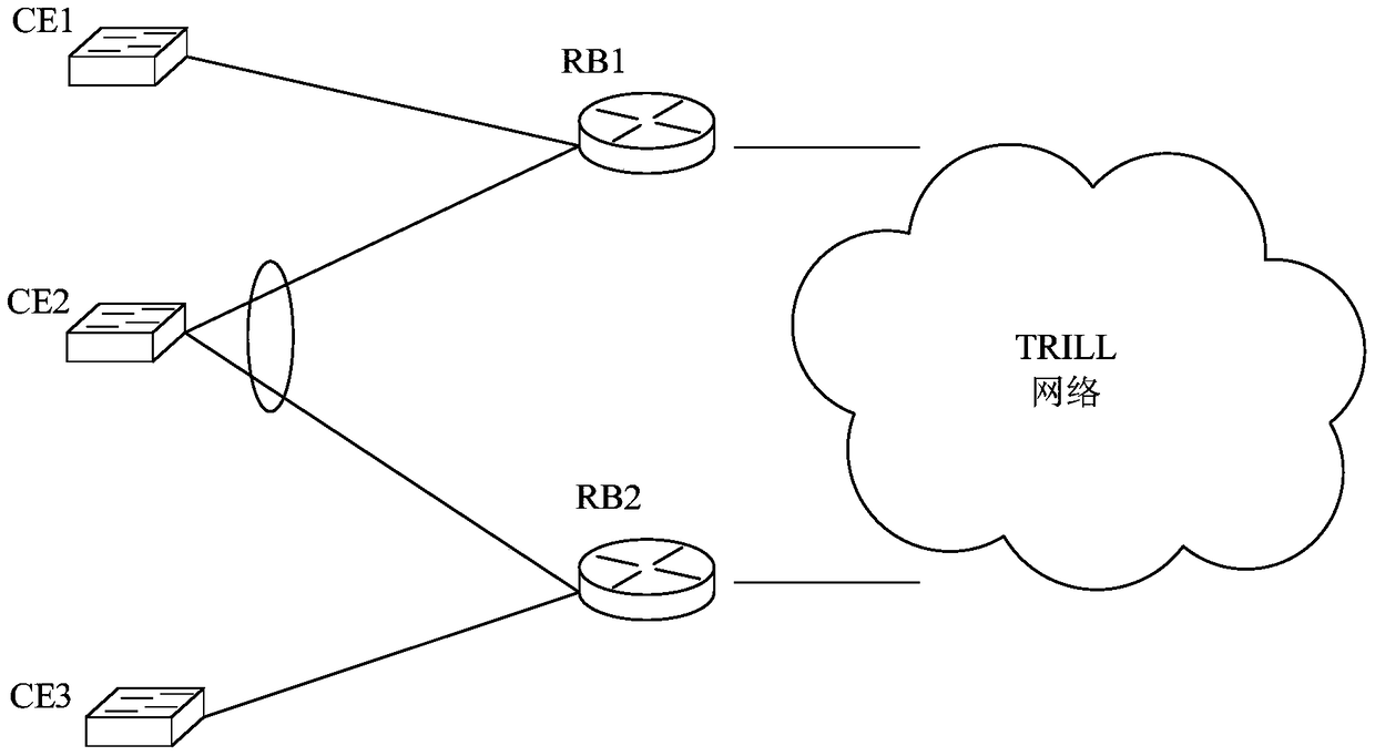
[0031] Step S101: The first switch receives a multicast message from the first user equipment or the second user equipment, wherein the first user equipment is single-homed to the first switch, and the second user equipment is multi-active connected to the network including the first switch. N switches, where N is greater than or equal to 2.

[0032] The first user equipment and the second user equipment are network edge devices on the user side, and may be routers, physical switches, or servers. The difference between the first user equipment and the second user equipment is: the first user equipment is only con...


PUM


Abstract

The invention discloses a method for sending a multicast message and a switch. The method includes receiving a multicast message from a first user equipment or a second user equipment, wherein the first user equipment is single-homed to the first switch, The second user equipment multi-active accesses N switches including the first switch; determines the designated multicast tree of the first switch, and the designated multicast tree is pre-designated from the N multicast trees that have been generated in the network, and N The switches belong to N different designated multicast trees respectively; the multicast message is encapsulated, and the unique identification address of the destination switch in the head of the encapsulated multicast message is the unique address of the root of the designated multicast tree of the first switch. Identifying the address; forwarding the encapsulated multicast message to the network side through the designated multicast tree of the first switch. Through the above method, the present invention can realize that the multicast message sent by the second user equipment does not return to the second user equipment itself through a loop without requiring a special chip.

Description

technical field [0001] The invention relates to the field of network technology, in particular to a method and switch for sending multicast messages. Background technique [0002] Transparent Interconnection of Lots of Links (English: Transparent Interconnection of Lots of Links, abbreviation: TRILL) is a new protocol for building a large-scale two-layer network. In the TRILL active-active scenario, user equipment (English: Customer Edge, Abbreviation CE) connects two routing bridges (English: Routing Bridge, abbreviation: RB) RB1 and RB2 for active-active networking. At this time, after the multicast packet sent by CE is encapsulated by RB1, it may be sent by RB1 to RB2, and then decapsulated by RB2 before being sent to the CE device. In this way, the CE device will receive the packets sent by itself, which will cause the circulation of multicast packets on the network, resulting in a waste of network resources. Therefore, this situation needs to be avoided. [0003] In ...

Claims


Application Information

Patent Timeline
15 Jun 2018
Publication
CN104954265B
IPC
H04L12/761; H04L12/46; H04L12/947; H04L45/16; H04L45/74
CPC
H04L12/6418; H04L45/66; H04L45/48; H04L45/16; H04L12/18; H04L45/74; H04L69/22; H04L49/201
Inventors
叢袅; 吴光锐