Eureka AIR delivers breakthrough ideas for toughest innovation challenges, trusted by R&D personnel around the world.

Interface and fluid-transfer system

一种流体传送、传送装置的技术,应用在仪器、机械设备、取样装置等方向,能够解决需要冲洗步骤、给定过程增加成本和复杂性、不期望停滞容积等问题

Active Publication Date: 2015-09-30
EMD MILLIPORE CORP
View PDF9 Cites 6 Cited by
  • Summary
  • Abstract
  • Description
  • Claims
  • Application Information

AI Technical Summary

Problems solved by technology

However, attachment through a manifold creates an undesirable stagnation volume (also known as a stagnation zone) and requires a flushing step, which adds cost and complexity to a given process
[0004] A disadvantage of many current sampling systems is that they require excessive processing, as all single-use sampling containers must be pre-attached immediately prior to the start of the process

Method used


Image

  • Interface and fluid-transfer system
  • Interface and fluid-transfer system
  • Interface and fluid-transfer system

Examples


Embodiment Construction

[0089] A description of example embodiments of the invention follows.

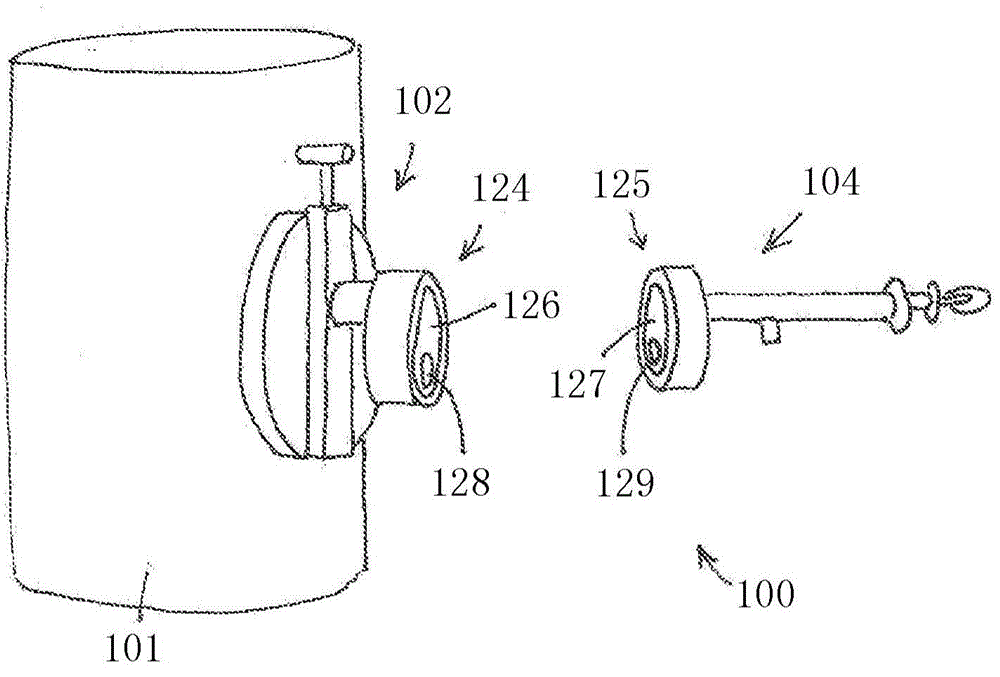
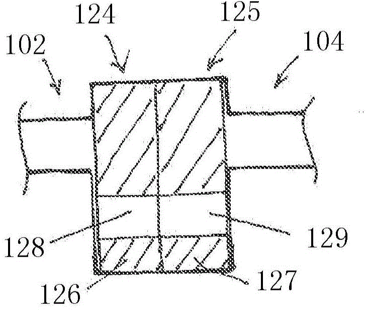
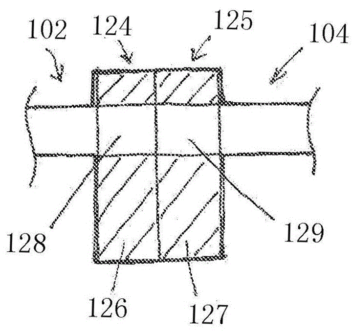
[0090] Figure 1A is a schematic diagram of an example fluid delivery system 100 according to one embodiment of the invention. Fluid delivery system 100 includes an interface device 102 to be mounted to a reservoir 101 and a delivery device 104 to be selectively coupled to interface device 102 . The interface device 102 includes a coupling member 124 including a sliding element 126 having an opening 128 . The transfer device 104 comprises a coupling element or member 125 comprising a sliding element 127 having an opening 129 . exist Figure 1A In , the interface device 102 and the transfer device 104 are shown uncoupled. Coupling members 124 and 125 are in their respective closed positions, opening 128 is out of alignment with interface device 102 , and opening 129 is out of alignment with delivery device 104 . The transfer coupling member 125 is configured to couple to the interface coupling member 124...


PUM


Abstract

A fluid transfer system (100) includes a transfer device (104) and an interface device (102). The transfer device (104) includes a fluid transfer member (164) and a transfer coupling member (125) to align the fluid transfer member (164) with the interface device (102). The interface device (102) includes a reservoir port (108), a fluid transfer member receptacle (144), an interface coupling member (124), and a reservoir valve (110). The interface coupling member (124) is configured to close the fluid transfer member receptacle (144) and to couple to the transfer coupling member (125) and open the fluid transfer member receptacle (144) to receive the fluid transfer member (164). The reservoir valve (110), e.g., a sliding seal, is configured to close the reservoir port (108) from the fluid transfer member receptacle (144) and to open the reservoir port (108) to the fluid transfer member (164) when the fluid transfer member (164) is positioned in the fluid transfer member receptacle (144). The fluid transfer member (164) can include a plunger assembly configured to open and close the reservoir port (108).

Description

[0001] related application [0002] This application claims the benefit of US Provisional Application No. 61 / 738,265, filed December 17, 2012. The entire teachings of the aforementioned applications are incorporated herein by reference. Background technique [0003] There are many sterilization and aseptic sampling systems on the market today. Sampling systems are often connected to the vessel by a sanitary connection (typically a standard port of 0.75", 1.5" or 2" in diameter). Some systems are actuated by a valve mechanism, while others employ a needle to pierce the septum. Typically , the number of samples that can be taken may be limited by any of the following: the size of the septum (multiple punctures at one site are generally unacceptable in the industry), the container that can be attached to the vessel (bag, bottles, etc.), and the size (diameter) of the tubing attached to the sanitary connections. Ability to take samples via manifold attachment when a particular p...

Claims


Application Information

Patent Timeline
Patent Type & Authority Applications(China)
IPC IPC(8): G01N1/10G01N1/22
CPCG01N1/2226G01N2001/1037G01N1/22G01N1/10F16K3/04
Inventor J·萨拉苟莎J·塞齐赫J·E·凯利L·梅西尔N·维戈里托
Owner EMD MILLIPORE CORP
Why Eureka
Eureka Blog
Learn More