Thin-wall inner flanging C-shaped steel truss connectors and composite truss

A technology of inward flanging and C-shaped steel, which is applied in the direction of truss structures, truss beams, joists, etc., can solve problems such as damage to the connecting structure, and achieve the effect of reducing self-weight, not easy to slip, and efficient construction

Active Publication Date: 2015-10-07
福建省绿筑低碳科技有限公司
View PDF9 Cites 9 Cited by
  • Summary
  • Abstract
  • Description
  • Claims
  • Application Information

AI Technical Summary

Problems solved by technology

[0005] The purpose of the present invention is to provide a thin-walled inner flanging C-shaped steel truss connector and a combined truss for the existing problems and deficiencies in the existing thin-walled steel structure connectors and connecting structures, which can avoid local damage to the connecting structure due to excessive pressure problems, and can be suitable for different steel connection requirements in order to reduce processing difficulty and reduce production costs

Method used


Image

  • Thin-wall inner flanging C-shaped steel truss connectors and composite truss
  • Thin-wall inner flanging C-shaped steel truss connectors and composite truss
  • Thin-wall inner flanging C-shaped steel truss connectors and composite truss

Examples


Embodiment 1

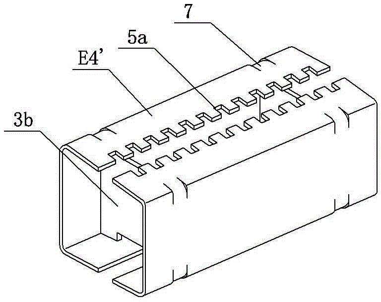
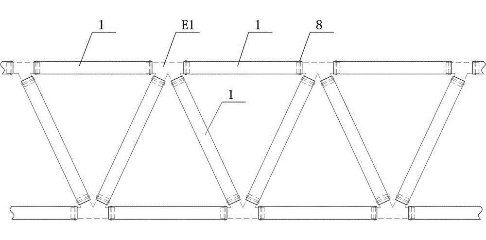
[0027] Embodiment 1: see image 3 and Figure 4 , the double thin-walled inner flanged C-shaped steel truss connector E1 with inner flanges is welded with at least two oblique plugs on the sides of two butted but gap-fitted channel-shaped steel plates. The corresponding plugs are buckled but fit in clearance; the inner side of the grooved steel plate and the oblique plug match the welding web at least at the end position, and the outer surface of the grooved steel plate and the oblique plug is provided with a positioning groove for punching or punching; each web An outwardly opening relief groove 4 is arranged between the plate and the grooved steel plate or the two side plates of the oblique plug. On the outside of the channel-shaped steel plate and the oblique plug, a locking groove 7 is arranged, and the locking groove 7 is arranged at a position corresponding to the web.

Embodiment 2

[0028] Example 2: see Figure 5 , single thin-walled inner flanged C-shaped steel truss connector E2 with inner flanged, at least two oblique plugs are welded on the side of a channel-shaped steel plate, the oblique plugs are groove-shaped, and the inner side of the channel-shaped steel plate and oblique plugs Match the welding web at least at the end position, and set punching or punching positioning grooves on the outer surface of the channel steel plate and the oblique plug; between each web and the two side plates of the channel steel plate or the oblique plug, there is an outward Opening give way slot4.

Embodiment 3

[0029] Embodiment 3: see Image 6 and Figure 7The structure of the double-thin-walled inner-flange C-shaped steel truss connector E3 with inner flanges is basically the same as that of the double-thin-walled inner-flange C-shaped steel truss connector E1 with inner flanges described in Embodiment 1. The difference is that the outer surface of the grooved steel plate and the oblique plug is provided with a positioning groove for punching. The punching positioning groove is located on the edge and has a convex-concave structure; it can be realized by punching or shearing. The webs of the connectors are connected to each other by reinforcing the connecting plates to increase their strength.


PUM


Abstract

The invention discloses thin-wall inner flanging C-shaped steel truss connectors and a composite truss. The composite truss comprises inner flanging C-shaped steel and the truss connectors. Inner flangings are arranged on side plates on the two sides of the inner flanging C-shaped steel respectively. The inner flanging C-shaped steel is inwards inserted into the outer sides of the truss connectors from the ends of the connectors respectively in a sleeving mode. The inner flanging C-shaped steel covers the outer sides of the truss connectors, and inner flangings are inserted into corresponding receding holes in a matched mode. Rear pressing grooves are formed in the surface of the inner flanging C-shaped steel and sleeved with stamped or punched positioning grooves in a matched mode. Steel belts are tied to the outer side of the inner flanging C-shaped steel, and the inner flanging C-shaped steel and the truss connectors are fixed together. The single inner flanging C-shaped steel is quickly and firmly in butt joint in an intersecting mode, or combined square steel is quickly and firmly in butt joint in an intersecting mode. The truss connectors are provided with webs, strength is high, and the truss connectors can serve as standard connecting pieces. The receding holes formed in the inner sides of the truss connectors and the inner flangings of the inner flanging C-shaped steel are buckled and compressed together, and the internal and external embedding effect is achieved. The positioning grooves formed in the outer sides of the truss connectors can be embedded in the inner flanging C-shaped steel in a concave-and-convex mode, and after compression and fixation are conducted through fastening of the steel belts, the fixing and anti-slipping effects are achieved.

Description

technical field [0001] The invention relates to the technical field of thin-walled steel structure building components, in particular to a thin-walled inner flanging C-shaped steel truss connector and a combined truss. Background technique [0002] The cold-formed thin-walled steel structure building system can adapt to complex building shapes due to its light weight, good seismic performance, and various connection forms. The characteristics of flexible layout, less construction waste, reusable components, and close to zero environmental pollution have attracted more and more attention, and have been listed as preferred projects in low-rise and mid-rise buildings. [0003] At present, the development and application of new high-strength cold-formed steel, especially thin-walled cold-formed steel, has become a new frontier in the field of cold-formed steel. However, in our country, the deep processing of product components in cold-formed thin-walled steel structures is not ...

Claims


Application Information

Patent Timeline
Patent Type & Authority Applications(China)
IPC IPC(8): E04C3/08
Inventor 魏群
Owner 福建省绿筑低碳科技有限公司
Why Eureka
Try Eureka