
A permanent magnet synchronous motor

A permanent magnet synchronous motor technology, applied in synchronous motors with static armatures and rotating magnets, magnetic circuit rotating parts, magnetic circuit shape/style/structure, etc., can solve the problem of starting torque of permanent magnet synchronous motors. Control, starting current is too large solid rotor, the centrifugal force of the iron core is too large, etc., to achieve the effect of improving the overall mechanical performance, reducing the damage effect, and controlling the fatigue damage

Active Publication Date: 2017-11-10
山西北方机械控股有限公司
View PDF8 Cites 0 Cited by
  • Summary
  • Abstract
  • Description
  • Claims
  • Application Information

AI Technical Summary

Problems solved by technology

[0005] The purpose of the present invention is to overcome the defects of the prior art, in order to solve the problem that the starting torque of the permanent magnet synchronous motor is difficult to control, the starting current is too large and the centrifugal force of the solid rotor core is too large to cause material fatigue, and a new type of permanent magnet is proposed. Synchronous Motor Structure

Method used


Image

  • A permanent magnet synchronous motor
  • A permanent magnet synchronous motor
  • A permanent magnet synchronous motor

Examples


Embodiment Construction

[0032] In order to make the object, technical solution and advantages of the invention clearer, the embodiments of the invention will be described in detail below in conjunction with the accompanying drawings.

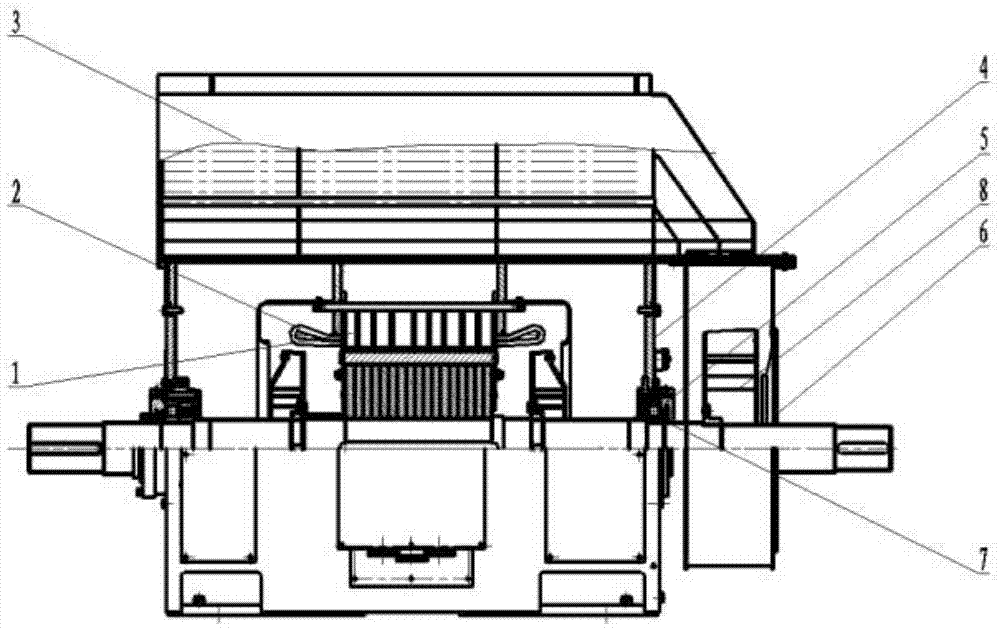
[0033] Such as figure 1 As shown, a permanent magnet synchronous motor consists of two major parts, the stator and the rotor. The stator part is composed of a casing, a stator core 1 and an armature winding 2 . The casing is composed of a casing 3, an end cover 4, a bearing cover 5, a fan cover 6 and an outer fan 8, and its structure is the same as that of an ordinary three-phase asynchronous motor. The stator of an ordinary three-phase asynchronous motor is directly assembled with the rotor part of the present invention to form a permanent magnet synchronous motor.

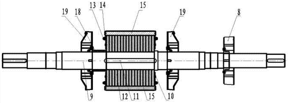
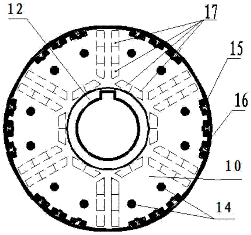
[0034] The focus of the invention is on the structural changes of the rotor components, such as figure 2 and image 3 As shown, the rotor components include a shaft 9, a key 11, a rotor core 12, a pe...


PUM


Abstract

The invention relates to a permanent magnet synchronous motor, and belongs to the technical field of a three-phase AC permanent magnet synchronous motor. The permanent magnet synchronous motor is composed of two major components of a stator and a rotor. The stator is composed of a machine shell, a stator iron core (1), an armature winding (2) and a machine base. The machine shell is composed of a shell (3), an end cap (4), a bearing cap (5) and a fan cover (6). The stator and the rotor are assembled via a bearing (7). The permanent magnet synchronous motor is characterized in that the rotor comprises a rotating shaft (9), a key (11), a rotor iron core (12), permanent magnets (17), small slot copper sheets (15), a double-end stud (13), a baffle plate (10), a sleeve ring (18), internal fans (19) and an external fan (8). Compared with permanent magnet synchronous motors in the prior art, starting torque and starting current of the motor can be effectively controlled by the permanent magnet synchronous motor, fatigue damage to material caused by iron core centrifugal force can be effectively controlled and the damage effect of the permanent magnets and a mouse cage can be reduced so that the permanent magnet synchronous motor has the effects of controlling electrical performance of the motor and enhancing the overall mechanical performance of the motor.

Description

technical field [0001] The invention relates to a permanent magnet synchronous motor, in particular to a rare earth NdFeB permanent magnet synchronous motor, which belongs to the technical field of three-phase AC permanent magnet synchronous motors. Background technique [0002] At present, three-phase asynchronous motors are mostly used in the industrial field, which has low efficiency, poor power factor, low starting torque multiple, and serious waste of energy. For various rare earth permanent magnet synchronous motors that have been successfully developed in recent years, the laminated magnetic pole rotors are mostly laminated with silicon steel sheets less than 1mm, which has the phenomenon of small starting torque and large starting current, which cannot meet the use of special working conditions; The solid rotor has large starting torque and large starting current, which is very easy to cause damage to the load equipment, and cannot achieve high efficiency and stabili...

Claims


Application Information

Patent Timeline
Patent Type & Authority Patents(China)
IPC IPC(8): H02K1/27H02K21/14
Inventor 武文虎邢明喜王志林冯雪山李有生李树龙薛维毅邢美栋赵瑜
Owner 山西北方机械控股有限公司
Learn More