A PWR Fuel Assembly Single-Metal Positioning Grid Resistant to Stress Fatigue
A technology for positioning grids and fuel components, applied to reactor fuel elements, assembly of fuel elements, reactors, etc., can solve problems such as fatigue cracks, increased cyclic stress of clamping structures, etc., and achieve ease of fretting abrasion and simple structure , Reduce the effect of flow-induced vibration
- Summary
- Abstract
- Description
- Claims
- Application Information
AI Technical Summary
Problems solved by technology
Method used
Image
Examples
Embodiment 1
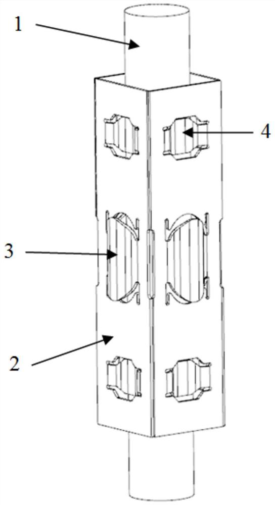
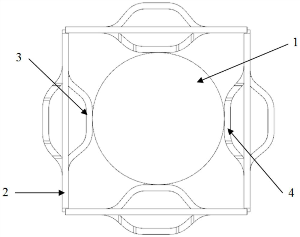
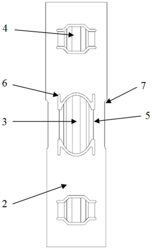
[0032] Such as Figure 1 to Figure 4 As shown, a single metal positioning grid of a pressurized water reactor fuel assembly resistant to stress fatigue includes strips 2 for surrounding the positioning grid, springs 3 are arranged on the strips 2, and springs 3 are arranged on the strips. A plurality of stress relief grooves on 2, the stress relief grooves are arranged around the spring 3: the spring 3 is located in the area surrounded by the plurality of stress relief grooves, and the stress relief grooves are all strip-shaped grooves running through the inside and outside of the strip 2.
[0033] In the prior art, in order to reduce the positioning damage and wear of the fuel rods 1, when designing the fuel assembly positioning grid, the springs 3 arranged on the strips 2 are generally adopted to have an overall lower stiffness. More specifically, in view of the above overall low stiffness characteristics, if the spring 3 is designed as a multi-bending structure as a whole, ...
Embodiment 2
[0036] The present embodiment is further limited on the basis of embodiment 1, as Figure 1 to Figure 4 As shown, as a specific solution of the spring 3 , it is set as follows: the spring 3 has an elliptical spherical shell structure, and the long axis direction of the spring 3 is parallel to the length direction of the strip 2 . In this solution, the above spring 3 not only has a simple structure, but also increases the contact length between the spring 3 on the positioning grid and the fuel rod 1, thereby reducing the abrasion depth corresponding to the same abrasion volume. By adopting this solution, the structural design of the spring 3 also has the characteristics of being convenient for pulling and inserting the fuel rod 1 . Combining the above technical scheme including stress relief grooves, in order to facilitate the description of the design features of this scheme, the following prior art is provided: "H" shaped spring 3 grids and "I" shaped spring 3 grids of Americ...
Embodiment 3
[0048] The present embodiment is further limited on the basis of embodiment 1, as Figure 1 to Figure 4 As shown: as a more complete technical solution for the positioning grid, it is set as follows: the positioning grid is a rectangular tube structure surrounded by four strips 2, and two springs 3 and four springs are arranged on the positioning grid. Rigid convex 4, each spring 3 is matched with two rigid convex 4, the matching spring 3 and rigid convex 4 have the following relationship: in the length direction of the strip 2, the spring 3 is located in the middle of one of the strips 2, and the rigid convex 4 The protrusion 4 is located on the opposite side of the spring 3, and both the upper and lower sides of the spring 3 have a rigid protrusion 4. This scheme provides a rectangular positioning grid. When the positioning grid is used in practice, the matching spring 3 and the rigid protrusion 4 form a clamping station for clamping the fuel rod 1, that is: this scheme prov...
PUM
 Abstract
Description
Claims
Application Information
 - R&D
- Intellectual Property
- Life Sciences
- Materials
- Tech Scout
- Unparalleled Data Quality
- Higher Quality Content
- 60% Fewer Hallucinations
Browse by: Latest US Patents, China's latest patents, Technical Efficacy Thesaurus, Application Domain, Technology Topic, Popular Technical Reports.
© 2025 PatSnap. All rights reserved.Legal|Privacy policy|Modern Slavery Act Transparency Statement|Sitemap|About US| Contact US: help@patsnap.com


