
Fixing guiding flexible puncture device

A flexible and oriented technology, applied in puncture needles, medical science, surgery, etc., can solve the problems of physical exertion, prolongation of time, prolongation of operation time, etc., and achieve the effect of flexible use, convenient puncture behavior, and a wide range of applications

Inactive Publication Date: 2015-10-14
李乐朋
View PDF8 Cites 10 Cited by
  • Summary
  • Abstract
  • Description
  • Claims
  • Application Information

AI Technical Summary

Problems solved by technology

On the market, there are few designs of fixed-guided puncture devices, and the design of some fixed-guided puncture devices cannot fully adapt to the continuous operation of the operator, which makes the operation time longer, and the patient and the operator need to consume more energy to complete the operation and be exposed to Extended time in radioactive environment

Method used


Image

  • Fixing guiding flexible puncture device
  • Fixing guiding flexible puncture device

Examples


Embodiment 1

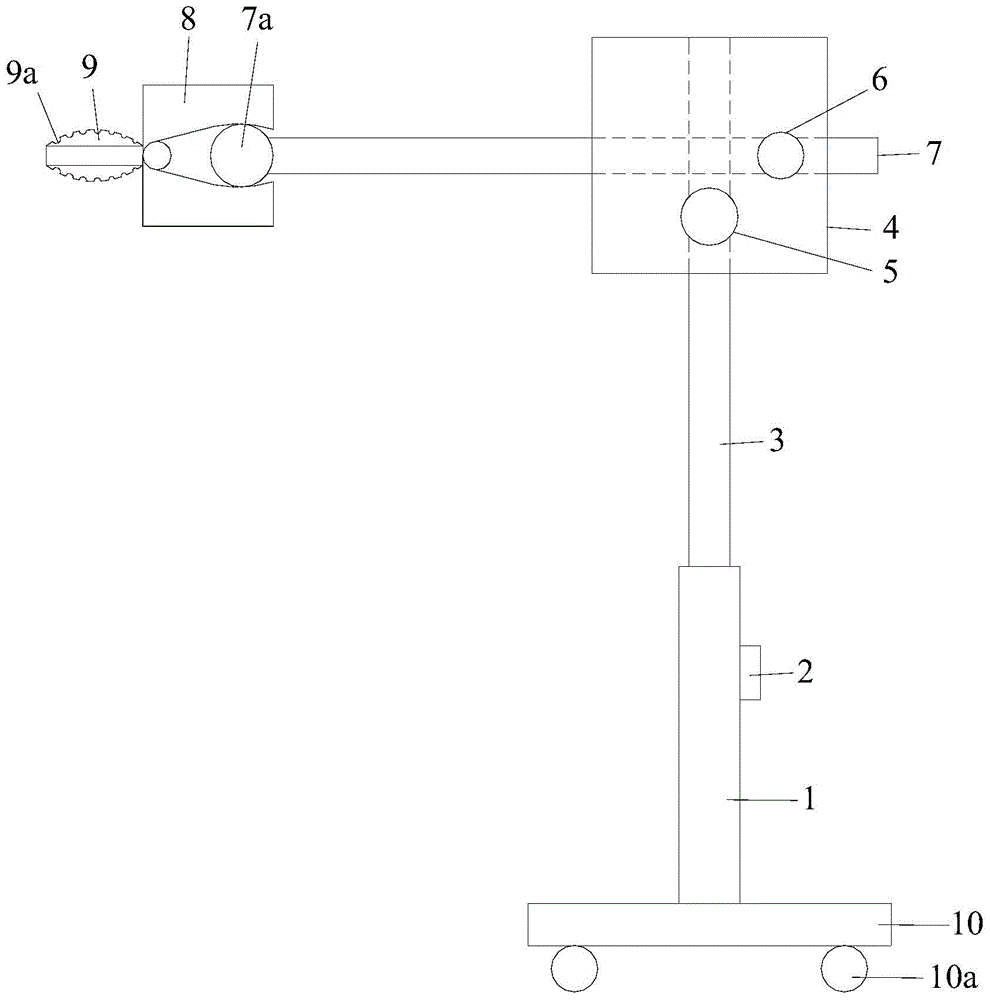
[0024] Please refer to figure 1 , the fixed-guided flexible puncture device includes a puncture frame and a puncture needle, and the puncture frame includes a sleeve 1, a lifting adjustment device 2, a vertical lifting frame 3, an adapter body 4, a rotating device, a fixing device 5, and a horizontal adjustment device. Device 6, horizontal telescopic frame 7, clamp type puncture fixed frame 8 and puncture guide frame 9.

[0025] The sleeve 1 is made of aluminum, and the side wall of the sleeve 1 is provided with a first installation hole.

[0026] The lifting adjustment device 2 is installed at the first installation hole of the sleeve 1 . The lifting adjustment device 2 is made of aluminum, and the lifting adjustment device 2 includes an operating part, a gear and a tooth groove structure. The operating part is a bolt. One end of the operating part is located outside the sleeve 1, and the other end of the operating part is installed from the first The hole extends into the ...

Embodiment 2

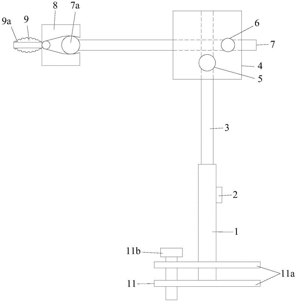
[0034] Please refer to figure 2 , the fixed-guided flexible puncture device includes a puncture frame and a puncture needle, and the puncture frame includes a sleeve 1, a lifting adjustment device 2, a vertical lifting frame 3, an adapter body 4, a rotating device, a fixing device 5, and a horizontal adjustment device. Device 6, horizontal telescopic frame 7, clamp type puncture fixed frame 8, puncture guide frame 9 and elastically adjustable fixed base frame 11.

[0035] The sleeve 1 is made of aluminum, and the side wall of the sleeve 1 is provided with a first installation hole. The lower end of the sleeve 1 is detachably mounted on the fixed chassis 1 .

[0036] The lifting adjustment device 2 is installed at the first installation hole of the sleeve 1 . The lifting adjustment device 2 is made of aluminum material. The lifting adjustment device 2 includes an operating part, a gear and a tooth groove structure. The operating part is a bolt and is made of aluminum materia...


PUM


Abstract

The present invention discloses a fixing guiding flexible puncture device. The device comprises a puncture frame and puncture needles, wherein the puncture frame comprises a vertical lifting frame, a change-over body, a horizontal expansion bracket, a puncture fixing support and a puncture guide support, wherein the change-over body can be installed on the upper end of the vertical lifting frame in a 360-degree freely rotating manner, a head end of the horizontal expansion bracket is telescopically installed on the change-over body, a head end of the puncture fixing support can be freely fixed on a tail end of the horizontal expansion bracket in all directions, the puncture guide support is fixedly connected at a tail end of the puncture fixing support, both an upper surface and a lower surface of the puncture guide support are provided with at least one puncture guide hole, and the puncture needles are installed on the puncture guide holes. The fixing guiding flexible puncture device provided by the present invention is convenient to operate, flexible to use, and convenient, rapid and stable in puncture actions, and guiding and fixing problems of the puncture needles in the puncture process are overcome.

Description

technical field [0001] The invention relates to a medical puncture device, in particular to a fixed-guided flexible puncture device. Background technique [0002] At present, percutaneous interventional surgery is widely used in the diagnosis and clinical treatment of tumors, blood vessels and other diseases. In order to complete the operation smoothly and accurately, a large number of devices are used in the operation process, such as puncture needles, puncture racks, probes, etc., and their arrangement and design greatly affect the ease and accuracy of the operator's operation. On the market, there are few designs of fixed-guided puncture devices, and the design of some fixed-guided puncture devices cannot fully adapt to the continuous operation of the operator, which makes the operation time longer, and the patient and the operator need to consume more energy to complete the operation and be exposed to Prolonged time in a radioactive environment. Contents of the invent...

Claims


Application Information

Patent Timeline
IPC IPC(8): A61B17/34
CPCA61B17/3403A61B2017/00831A61B2017/3405
Inventor 李乐朋
Owner 李乐朋
Learn More