Magnet mutual effect tester
An experimental device and magnet technology, applied in the direction of instruments, educational appliances, teaching models, etc., can solve the problems that students are difficult to observe clearly, troublesome to operate, and inconvenient to move to classrooms of each class, etc. small effect
Inactive Publication Date: 2015-10-14
王蕴红
View PDF0 Cites 1 Cited by
- Summary
- Abstract
- Description
- Claims
- Application Information
AI Technical Summary
Problems solved by technology
[0003] This experimental method requires an iron stand, which is not convenient to move it from the laboratory to each classroom, and the operation is also troublesome
In particular, the suspended magnet can only rotate in the horizontal plane, and it is difficult for most students to clearly observe the difference between "closer" and "away"
Method used
View moreImage
Smart ImageViewing Examples

Examples
Embodiment Construction
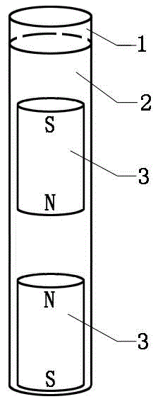
[0010] Such as figure 1 As shown, a pair of magnets 3 are placed in the transparent cylinder 2 . The transparent cylinder 2 is equipped with a cylinder cover 1 for convenient storage of the internal magnet 3 .
[0011] The magnet 3 can be a cylindrical magnet or a rectangular parallelepiped magnet.
Login to View More PUM
 Abstract
Disclosed is a magnet mutual effect tester. The magnet mutual effect tester comprises a pair of bar magnets, and is characterized by further comprising a transparent cylinder for accommodating the magnets, wherein the internal diameter of the transparent cylinder is greater than the maximum transverse dimension of the magnets and is smaller than the length of the magnets, and the transparent cylinder is made of plastics and is provided with a cylinder cover. The The magnet mutual effect tester has the following advantages: since the internal diameter of the transparent cylinder is smaller than the length of the magnets, the magnets can only slide in the transparent cylinder and cannot reverse to opposite-polarity magnetic poles for attraction, when the transparent cylinder is vertically placed, an upper-surface magnetic pole is suspended at an upper position, the transparent cylinder is reversed, a magnet originally arranged at a lower position can also be suspended in the air, it is visually and vividly indicated that same-polarity magnetic poles repulse each other, and students are impressed and can have a better understanding. The apparatus is small, can be placed in a pocket and is conveniently carried. Since the plastic cylinder is not easily damaged, the magnet mutual effect tester is durable.
Description
technical field [0001] The invention relates to a physics teaching instrument, in particular to an experimenter for interaction between magnets. Background technique [0002] In the existing junior high school physics experiment of "mutual repulsion of magnetic poles with the same name", the usual method is: hang a bar magnet on the iron stand with a thin wire, and then use the magnetic pole of the same name of another bar magnet to approach it , it will be found that the suspended magnet will move away during the rotation, indicating that the suspended magnet is affected by repulsive force; then exchange the two magnets, hang the original hand-held magnet, and hold the original suspended magnet in your hand to approach, the suspended magnet The photograph will be far away, indicating that the repulsive force between the two magnets interacts. [0003] This experimental method requires an iron stand, which is inconvenient to move from the laboratory to the classrooms of eac...
Claims
Login to View More Application Information
Patent Timeline
 IPC IPC(8): G09B23/18
Inventor 王蕴红
Owner 王蕴红