Non-inverting domino register

a register and domino technology, applied in the field of dynamic logic and register functions, can solve the problems of significant slower operating speed, additional delay in the register, designers forced to deal with disadvantageous consequences, etc., and achieve the effect of minimizing delay and small devices

Active Publication Date: 2007-03-20
IP FIRST
View PDF16 Cites 6 Cited by
  • Summary
  • Abstract
  • Description
  • Claims
  • Application Information

AI Technical Summary

Benefits of technology

[0016]The non-inverting domino register may be implemented using P-channel and N-channel devices. For example, the complementary pair of evaluation devices, the storage stage and the output stage may each be implemented using P-channel and N-channel devices. The evaluation logic may range from very simple to very complex, and may be, for example, a complex logic circuit. In one embodiment, the keeper circuit is a pair of inverters cross-coupled between the first and second preliminary output nodes. The inverters may be relatively small devices to minimize delay. The feedback inverter of the keeper may be replace with an enabled inverter.

Problems solved by technology

Preceding and following a logical evaluation circuit with traditional register circuits introduces delays into a pipeline system whose cumulative effect results in significantly slower operating speeds.
More specifically, one notable source of these delays is the data-to-output time requirements that must be satisfied by logical evaluation circuits in order to ensure stable registered outputs.
In cases in which a non-inverted registered output is required, however, designers have been forced to deal with disadvantageous consequences.
To produce the non-inverted output Q, designers typically had to add the inverter 115 to invert QB to provide the non-inverted output Q. This workaround, however, inserted additional delay to the register.
The delays are increased using larger buffer devices with increased capacitance.
Nonetheless, the total delay remains significant for the non-inverting case.
This second alternative, however, exposes the weak keeper circuit 111 to noise conditions under which the stability of the QBI signal is put at risk.

Method used


Image

  • Non-inverting domino register
  • Non-inverting domino register
  • Non-inverting domino register

Examples


Embodiment Construction

[0027]The following description is presented to enable one of ordinary skill in the art to make and use the present invention as provided within the context of a particular application and its requirements. Various modifications to the preferred embodiment will, however, be apparent to one skilled in the art, and the general principles defined herein may be applied to other embodiments. Therefore, the present invention is not intended to be limited to the particular embodiments shown and described herein, but is to be accorded the widest scope consistent with the principles and novel features herein disclosed.

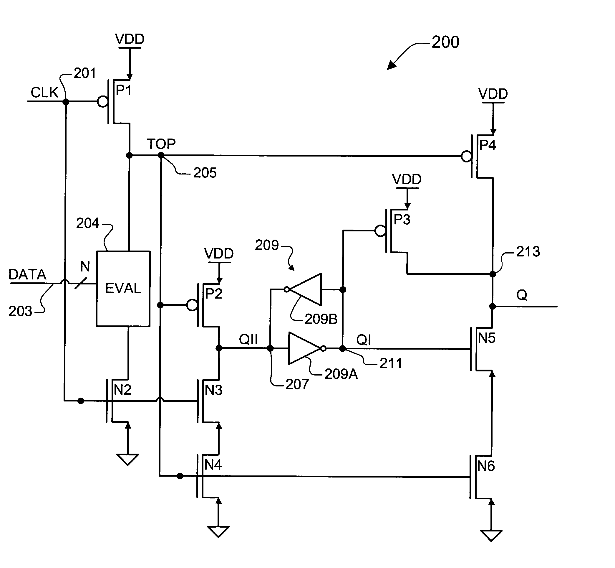
[0028]The inventor of the present application has recognized the need for providing registered outputs for logic circuits in which speed, size and stability are critical factors. He has therefore developed a non-inverting domino register that has a faster data-to-output time than conventional approaches without compromising the stability of the output, as will be further descri...


PUM


Abstract

A non-inverting domino register including a domino stage, a storage stage, a keeper circuit and an output stage. The domino stage includes evaluation logic, coupled between evaluation devices at a pre-charged node, which evaluates a logic function. The storage stage drives a first preliminary output node and includes a pull-up device and a pull-down device both responsive to the pre-charged node, and a second pull-down device responsive to the clock signal. The keeper circuit is a cross-coupled pair of inverters coupled between the first preliminary output node and a second preliminary output node. The output stage includes a pair of pull-up and pull-down devices for driving an output node. The first pull-up device and the first pull-down device are both responsive to the pre-charged node, and the second pull-up device and the second pull-down device are both responsive to the second preliminary output node.

Description

CROSS-REFERENCE TO RELATED APPLICATIONS[0001]This application claims the benefit of U.S. Provisional Application No. 60 / 402962, filed on Aug. 14, 2002, which is herein incorporated by reference for all intents and purposes.BACKGROUND OF THE INVENTION[0002]1. Field of the Invention[0003]The present invention relates to dynamic logic and register functions, and more particularly to a non-inverting domino register that addresses the problem of registering the outputs of complex logic circuits where speed and size are important factors.[0004]2. Description of the Related Art[0005]Integrated circuits use a remarkable number of registers, particularly those having a synchronous pipeline architecture. Register logic is employed to hold the outputs of devices and circuits for a period of time so that these outputs can be received by other devices and circuits. In a clocked system, such as a pipeline microprocessor, registers are used to latch and hold the outputs of a given pipeline stage f...

Claims


Application Information

Patent Timeline
Patent Type & Authority Patents(United States)
IPC IPC(8): H03K19/096H03K19/20
CPCH03K19/0963
Inventor BERTRAM, RAYMOND A.
Owner IP FIRST
Why Eureka
Try Eureka