
Linkage component of switching device group and switching device group thereof

A technology of switching devices and linkage components, which is applied in the direction of electrical components, electric switches, circuits, etc., can solve the problem of long transmission distance of rotation motion, achieve the effect of avoiding huge torque, avoiding damage, and improving synchronization

Inactive Publication Date: 2019-03-15
SIEMENS AG
View PDF6 Cites 0 Cited by
  • Summary
  • Abstract
  • Description
  • Claims
  • Application Information

AI Technical Summary

Problems solved by technology

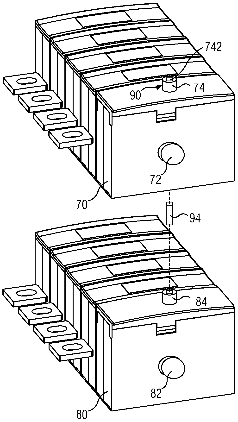
[0004] However, in the above-mentioned synchronous operation process, since the switching device requires a large operating force when passing through the dead point position, in the process of transmitting the rotational motion from the first drive shaft 74 to the second drive shaft 84, the first drive shaft 74 needs to withstand the operating force that can operate the two switching devices, and the operating end 742 of the first drive shaft 74 is far away from the second drive shaft 84, resulting in a long transmission distance of the rotational motion

Method used


Image

  • Linkage component of switching device group and switching device group thereof
  • Linkage component of switching device group and switching device group thereof
  • Linkage component of switching device group and switching device group thereof

Examples


Embodiment Construction

[0070] In order to have a clearer understanding of the technical features, purposes and effects of the invention, the specific embodiments of the present invention are now described with reference to the accompanying drawings, in which the same reference numerals represent components with the same or similar structures but the same functions.

[0071] In this article, "schematic" means "serving as an example, example or illustration", and any illustration or implementation described as "schematic" should not be interpreted as a more preferred or more advantageous Technical solutions.

[0072] In order to make the drawing concise, each drawing only schematically shows the parts related to the present invention, and they do not represent the actual structure of the product. In addition, in order to make the drawings concise and easy to understand, in some drawings, only one of the components having the same structure or function is schematically shown, or only one of them is mar...


PUM


Abstract

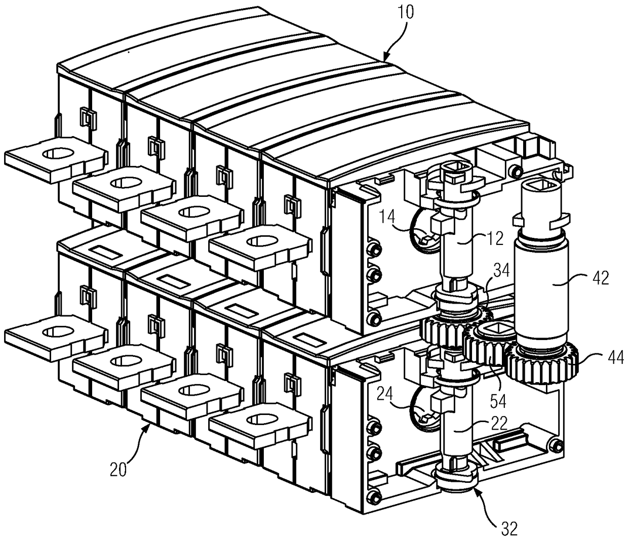
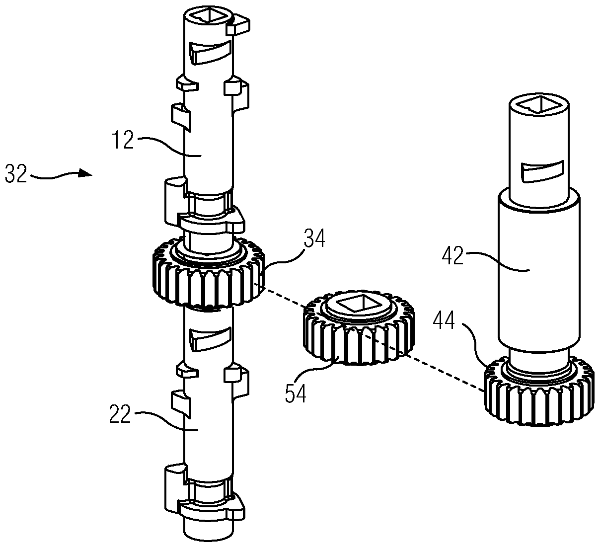
The invention provides a linkage assembly of a switching device set, wherein the switching device set comprises a first switching device (10), a second switching device (20) and a main driving shaft (32) which rotatably penetrates through the first switching device and the second switching device. The main driving shaft comprises a first driving shaft (12) and a second driving shaft (22) which can be coaxially connected with the first driving shaft. The linkage assembly comprises an operation shaft (42), a first linkage member (44) and a second linkage member (34). The first linkage member can be connected with the operation shaft and rotates together with the operation shaft. The second linkage member can be connected with the main driving shaft of the switching device set and rotates together with the main driving shaft. The second linkage member is arranged at the connection part between the first driving shaft and the second driving shaft and can be transmissibly connected with the first linkage member. By means of the first linkage member and the second linkage member, rotation of the operation shaft can drive the main driving shaft to rotate. The linkage assembly can improve operation synchronism of the switching device set.

Description

technical field [0001] The invention relates to a linkage assembly, in particular to a linkage assembly of a switching device group. The present invention also relates to a switching device set having the above-mentioned linkage assembly. Background technique [0002] In the switching device, by operating the drive shaft to switch between the open position and the closed position, the drive shaft is driven to make the movable contact contact and separate from the fixed contact, thereby controlling the switching device to be closed or disconnected, so as to realize the on-off of the power supply line electric control. [0003] When it is necessary to realize the synchronous operation of two switching devices, due to the limitation of structural arrangement, such as figure 1 As shown, the two switching devices of the general switching device group are arranged up and down, and the transmission shaft 72 of the upper switching device 70 and the transmission shaft 82 of the low...

Claims


Application Information

Patent Timeline
Patent Type & Authority Patents(China)
IPC IPC(8): H01H9/24
Inventor 刘云内斯·弗朗茨宋建康何俊杰沈建良温克勒·亚历山大
Owner SIEMENS AG
Learn More