High-dispersibility vortex powder selecting machine

A high-dispersity, powder-separator technology, applied in solid separation, separation of solids from solids by air flow, chemical instruments and methods, etc. question

Inactive Publication Date: 2015-10-21
JIANGSU JINENGDA ENVIRONMENTAL ENERGY SCI & TECH
View PDF7 Cites 7 Cited by
  • Summary
  • Abstract
  • Description
  • Claims
  • Application Information

AI Technical Summary

Problems solved by technology

In the above-mentioned O-Sepa powder separator, the material entering from the top feed port is scattered to the surroundings through the spreading plate on the top of the cage-shaped rotor. In the powder selection area between the air guide vane and the rotor, the material curtain falling between the air guide vane and the rotor is relatively thick, so not only the powder selection efficiency is low, but also the classification accuracy is high; at the same time, due to the For top feeding, there is often a phenomenon of material aggregation between the guide vane and the shell, which greatly affects the powder selection efficiency

Method used


Image

  • High-dispersibility vortex powder selecting machine
  • High-dispersibility vortex powder selecting machine

Examples


Embodiment Construction

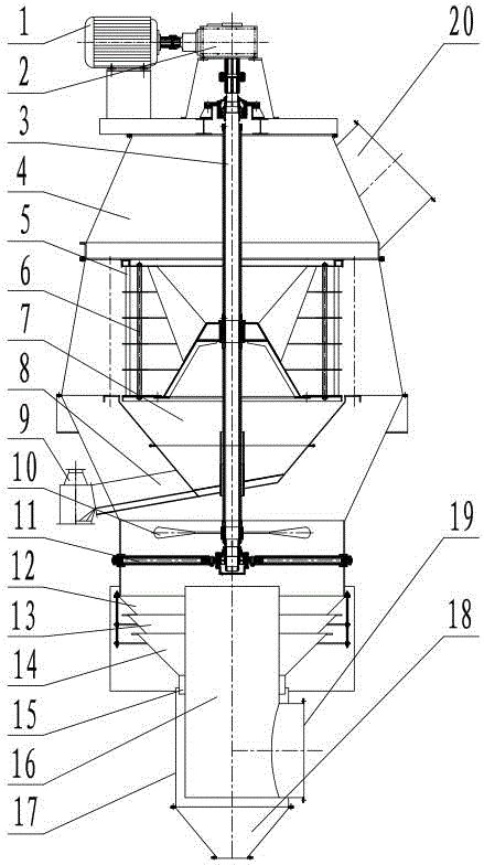
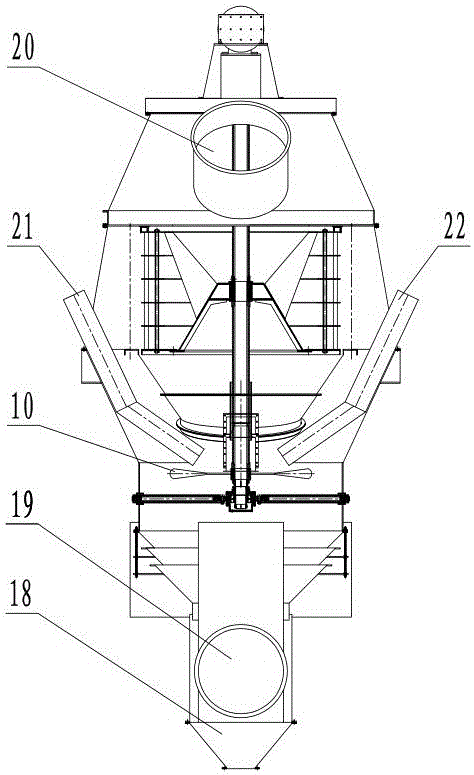
[0010] figure 1 with figure 2 Among them, the high-dispersion eddy current powder separator includes a housing 4, a cage rotor 6, a motor 1, a reduction box 2, a transmission shaft 3, a feeding pipe, an air outlet pipe 20, a spreading disc 10, an air guide vane 5 and Meal collection cone 18. Both the motor 1 and the reduction box 2 are arranged on the top of the casing 4 . The motor 1 is connected to the reduction box 2, the upper end of the transmission shaft 3 is connected to the reduction box 2, the lower end of the transmission shaft 3 passes through the top of the casing 4 and is located in the casing 4, and the cage rotor 6 is arranged on the transmission shaft 3, and the cage rotor The outer side of 6 is equipped with a circle of described guide blades 5.

[0011] The above-mentioned high-dispersibility eddy current powder separator also includes a medium and coarse powder collecting cone 7, an upper collecting cone 12, a middle collecting cone 13, a lower collectin...


PUM


Abstract

The invention discloses a high-dispersibility vortex powder selecting machine. The high-dispersibility vortex powder selecting machine comprises a shell, a cage-shaped rotor, a motor, a speed reduction box, a transmission shaft, a feeding pipe, an air outflow pipe, a scattering plate, air guiding blades and a coarse powder collecting cone and further comprises a medium coarse powder collecting cone, an upper collecting cone, a middle collecting cone, a lower collecting cone, an outer barrel, an air inflow pipe and a powder passing pipe. The medium coarse powder collecting cone is located below the cage-shaped rotor. The lower end of the transmission shaft extends to the inner lower portion of the shell and is installed in a bearing pedestal. The scattering plate is arranged at the lower end of the transmission shaft. The upper collecting cone, the middle collecting cone and the lower collecting cone are sequentially arranged on the inner lower portion of the shell from top to bottom. An upper opening of the outer barrel is connected with the lower end of the powder passing pipe. A lower opening of the outer barrel is connected with an upper opening of the coarse powder collecting cone. The air inflow pipe is located in the outer barrel. A coarse powder channel is reserved between the air inflow pipe and the inner wall of the outer barrel, and a coarse powder channel is reserved between the air inflow pipe and the inner wall of the powder passing pipe. The feeding pipe is arranged on the shell in a penetrating mode. A discharging port of the feeding pipe is located in the shell and above the scattering plate. The air outflow pipe is located on the upper portion of the shell.

Description

technical field [0001] The invention relates to a powder separator, in particular to a highly dispersive eddy current powder separator. Background technique [0002] At present, in the cement production process, the equipment used includes a powder separator, which is usually an O-Sepa powder separator, which contains a shell with a cage-shaped rotor inside, and a sprinkler on the upper part of the cage-shaped rotor. The material tray, the outer ring of the rotor is equipped with a circle of guide blades, the top of the casing is provided with an air outlet pipe and a feed port, and the lower part of the rotor is a coarse powder cone. Working principle: The selected material enters from the feeding port on the top of the shell and falls on the rotating spreading plate. Due to the action of centrifugal force, the material is thrown out and hits the buffer plate to change direction and fall freely. A material curtain is formed in the annular space between them. The primary a...

Claims


Application Information

Patent Timeline
Patent Type & Authority Applications(China)
IPC IPC(8): B07B9/02B07B7/01B07B7/083B07B11/02
Inventor 吕海峰曹海宁徐中州
Owner JIANGSU JINENGDA ENVIRONMENTAL ENERGY SCI & TECH
Why Eureka
Try Eureka