
Small-space automatic tube expansion robot

A robot and small space technology, applied in the field of boilers, can solve the problems of inconvenient manual expansion operation, narrow header space, poor working conditions, etc., to reduce the waiting time for cooling, reduce labor intensity, and automatically control the expansion rate.

Active Publication Date: 2015-10-21
HARBIN HAGUO BOILER ENG TECH
View PDF5 Cites 2 Cited by
  • Summary
  • Abstract
  • Description
  • Claims
  • Application Information

AI Technical Summary

Problems solved by technology

[0003] The present invention aims to solve the problem that the expansion joint structure is adopted between the piping pipe and the header of the existing naval boiler. Due to the narrow space in the header and the harsh working conditions, it is very inconvenient to manually expand the joint operation, and further proposes a small space Automatic Tube Expansion Robot

Method used


Image

  • Small-space automatic tube expansion robot
  • Small-space automatic tube expansion robot
  • Small-space automatic tube expansion robot

Examples


specific Embodiment approach 1

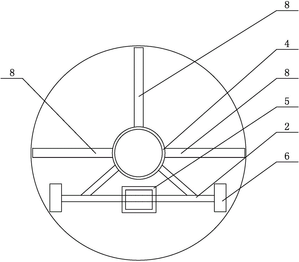
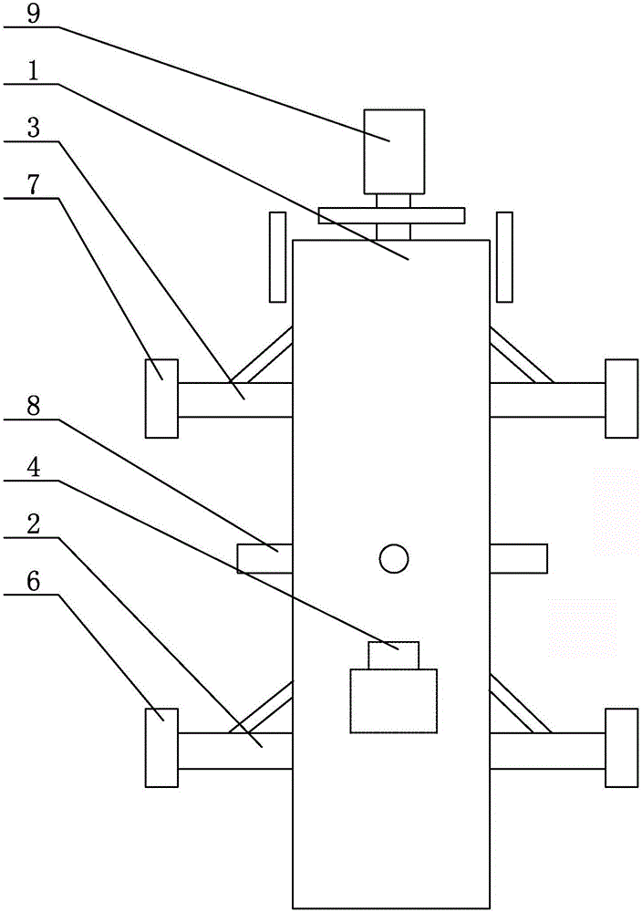
[0007] Specific implementation mode one: combine figure 1 with figure 2 Describe this embodiment, a small-space automatic tube expanding robot described in this embodiment includes a robot main body 1, a walking driving shaft 2, a walking driven shaft 3, a walking hydraulic motor 4, a gearbox 5, a tube expander connecting mechanism, two A walking driving wheel 6, two walking driven wheels 7 and three fixed support cylinders 8, the walking driving shaft 2 and the walking driven shaft 3 are installed side by side in parallel on the robot main body 1 from front to back, and the walking driving shaft 2 The axes of the axis and the walking driven shaft 3 are perpendicular to the center line of the robot main body 1 along the length direction. A walking driving wheel 6 is respectively installed at both ends of the walking driving shaft 2, and a walking driving wheel 6 is respectively installed at both ends of the walking driven shaft 3. Walking driven wheel 7, walking hydraulic mo...

specific Embodiment approach 2

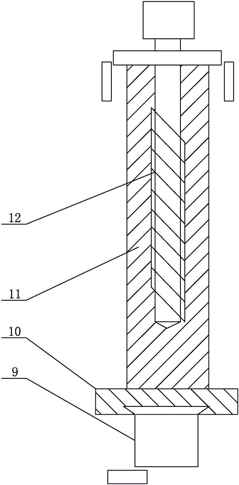
[0008] Specific implementation mode two: combination image 3 Describe this embodiment, the tube expansion connection mechanism of a small-space automatic tube expansion robot described in this embodiment includes a tube expander hydraulic motor 9, a slideway 10, a connecting shaft 11 and a lead screw 12, and the tube expander hydraulic motor 9 and The slideway 10 is connected, the slideway 10 is connected with one end of the connecting shaft 11 , and the lead screw 12 is inserted in the other end of the connecting shaft 11 .

[0009] In this embodiment, the slideway 10 is provided with a jacking cylinder. Other components and connections are the same as those in the first embodiment.

[0010] working principle

[0011] Step 1. Install the tube expander on the tube expander connection mechanism, start the walking hydraulic motor 4, and the walking hydraulic motor 4 drives the robot main body 1 to the tube expansion area, and control the tube expansion within the range of ±10...


PUM


Abstract

The invention relates to an automatic tube expansion robot, in particular to a small-space automatic tube expansion robot. The problems that an expanded connection structure is adopted between pipelines and headers of existing ship boilers, and due to the fact that space in the headers is narrow and work conditions are severe, manual expanded connection operation is quite inconvenient are solved. The small-space automatic tube expansion robot comprises a robot body, a walking driving shaft, a walking driven shaft, a walking hydraulic motor, a gearbox, a tube expander connecting mechanism, two walking driving wheels, two walking driven wheels and three fixed supporting air cylinders. The walking driving shaft and the walking driven shaft are sequentially arranged on the robot body from front to back side by side in parallel, the axis of the walking driving shaft and the axis of the walking driven shaft are perpendicular to the center line, in the length direction, of the robot body, the two ends of the walking driving shaft are each provided with one corresponding walking driving wheel, and the two ends of the walking driven shaft are each provided with one corresponding walking driven wheel. The small-space automatic tube expansion robot is used for tube expansion.

Description

technical field [0001] The invention relates to an automatic tube expanding robot, in particular to an automatic tube expanding robot in a small space, which belongs to the field of boilers. Background technique [0002] Ship boilers with a displacement of more than 10,000 tons are compact in structure and small in space. The boiler tube and header adopt an expansion joint structure, and the inner space of the header can only allow one person to drill in. The working conditions were very poor. Existing expansion joint machines in small spaces and headers use external power heads to transmit power to the transmission box inside the equipment through the transmission rod, and people hold the transmission box with their hands for expansion. Due to the narrow space inside the equipment, the working environment for people inside the equipment is very harsh. The transmission box weighs 7 kilograms, and each person can only insist on expanding and connecting about 5 pipes. If th...

Claims


Application Information

Patent Timeline
IPC IPC(8): B21D39/08
CPCB21D39/20
Inventor 于海波韩蕴绮祝应时顾锦辉
Owner HARBIN HAGUO BOILER ENG TECH
Features
  • Generate Ideas
  • Intellectual Property
  • Life Sciences
  • Materials
  • Tech Scout
  • Unparalleled Data Quality
  • Higher Quality Content
  • 60% Fewer Hallucinations
Learn More