Manual permanent magnet sand sucker and application method thereof

A sand suction and permanent magnet technology, applied in the field of manual permanent magnetic sand suction, can solve the problems of abnormal system operation, increase production cost, disadvantageous mass production, etc., and achieve the best sand suction effect.

Inactive Publication Date: 2015-10-21
QINGDAO WUCHUAN HEAVY IND CO LTD
View PDF8 Cites 0 Cited by
  • Summary
  • Abstract
  • Description
  • Claims
  • Application Information

AI Technical Summary

Problems solved by technology

However, it is difficult for large equipment to clear corners, gaps and other places that are not easy to construct
It can only be carried out by hand tools such as scrapers and shovels, so there are the following disadvantages: First, the labor intensity is high and the work efficiency is low, which is not conducive to mass production; it may even cause early failure of parts and abnormal operation of the system Wait for the consequences
And because the corners, crevices and other positions are difficult to clean, it also causes a waste of steel grit
Increase production cost, and also easily pollute equipment and environment
[0003] In order to solve the above problems, some enterprises use high-pressure airflow to spray glass balls into areas that are difficult to clean, such as the device in the inner cavity of castings, which can clean the sand in the inner cavity, but the glass balls will be broken and often sprayed out, so the cost of use is relatively high. High, poor security
Individual companies even use ultrasonic sand cleaning equipment to clean the inner cavity, but the equipment is expensive, one-time investment is large, and the cost of use is high

Method used


Image

  • Manual permanent magnet sand sucker and application method thereof
  • Manual permanent magnet sand sucker and application method thereof
  • Manual permanent magnet sand sucker and application method thereof

Examples


Embodiment Construction

[0036] The present invention will be described in further detail below in conjunction with the accompanying drawings and embodiments.

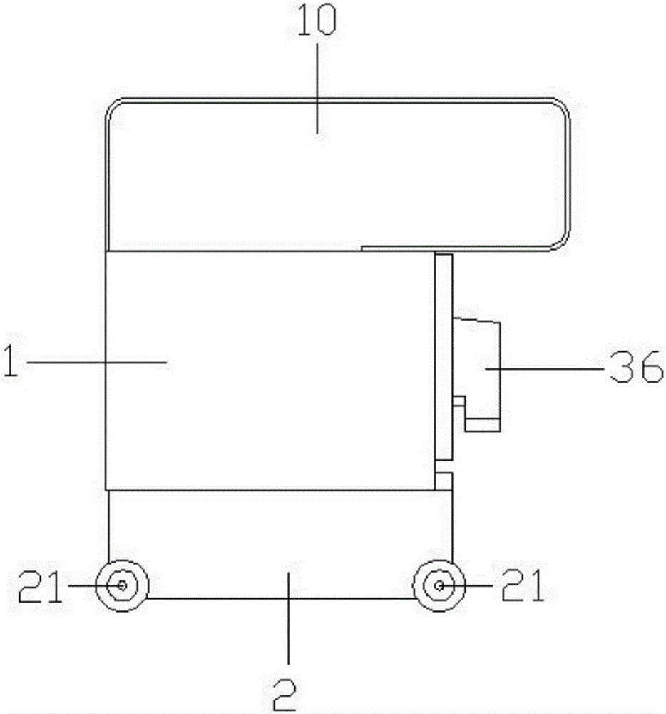
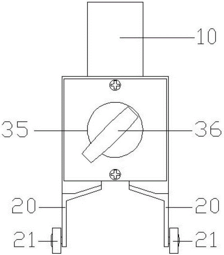
[0037] see figure 1 with figure 2 As shown, a manual permanent magnetic sand sucker of the present invention includes a main body 1, the main body 1 is a hollow shell, and the hollow part of the shell forms a storage space; the upper end of the main body 1 is provided with a hand-held part 10, A support 2 is fixed on the lower surface. The bracket 2 is composed of two parallel support frames 20 , and the two support frames 20 are respectively fixed on both sides of the lower surface of the main body part 1 . Wherein, the materials of the two supporting frames 20 are both A3 steel. The supporting frame 20 is provided with rollers 21, which is convenient for users to operate.

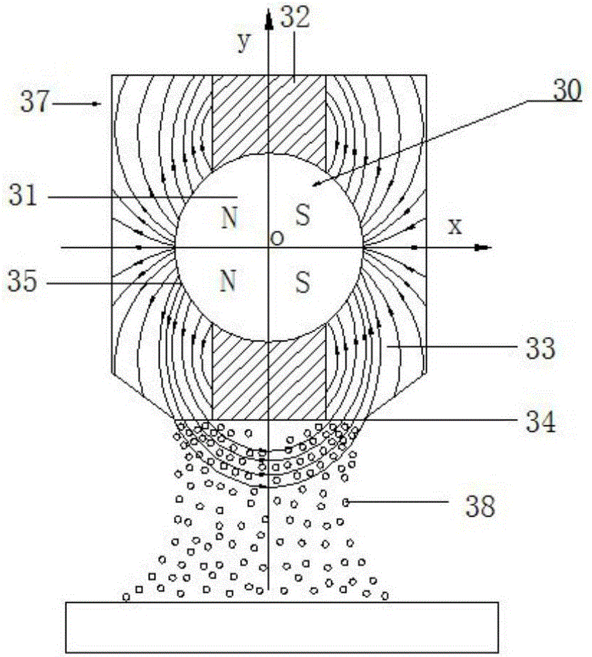
[0038] Please also refer to Figure 1 to Figure 4 A magnetic sand-absorbing device 3 is housed in the housing space of the main body 1 , and the magnetic sand-absor...


PUM


Abstract

The invention discloses a manual permanent magnet sand sucker. The manual permanent magnet sand sucker comprises a body part including an accommodating space, a bracket fixed on the body part, and a magnetic sand sucking device accommodated in the accommodating space, wherein the magnetic sand sucking device comprises a permanent magnet, isolate magnets arranged at the upper and lower ends of the permanent magnet, and magnetizers arranged at the left and right sides of the permanent magnet; the magnetizers and the isolate magnets define a cavity having an accommodating channel; the permanent magnet is accommodated in the accommodating channel, and can rotate in the accommodating channel; and meanwhile, the permanent magnet consists of four sub-permanent magnets with magnetic poles as NNSS in sequence in the rotating direction. Compared with other sand removing devices, the manual permanent magnet sand sucker is free of environmental pollution; and the four sub-permanent magnets can rotate in the cavity consisting of the isolate magnets and the magnetizers, so that the manual permanent magnet sand sucker can conveniently suck and unload sands.

Description

technical field [0001] The invention relates to the field of steel sand cleaning equipment after steel surface treatment, in particular to a manual permanent magnetic sand suction device and a use method thereof. Background technique [0002] At present, there are many sand cleaning devices, such as shot blasting machines for cleaning the shape of castings. Large-scale components such as large steel plates also have large-scale sand cleaning equipment for sand cleaning. However, it is difficult for large equipment to clear corners, gaps and other places that are not easy to construct. It can only be carried out by hand tools such as scrapers and shovels, so there are the following disadvantages: First, the labor intensity is high and the work efficiency is low, which is not conducive to mass production; it may even cause early failure of parts and abnormal operation of the system Wait for the consequences. And because the corners, gaps and other positions are difficult to...

Claims


Application Information

Patent Timeline
IPC IPC(8): B24C9/00
CPCB24C9/00H01F7/02
Inventor 李超易平洋杨生威
Owner QINGDAO WUCHUAN HEAVY IND CO LTD
Why Eureka
Try Eureka