Opposite roller type smashing sand making machine

A technology of sand making machine and roller type, which is applied in the direction of grain processing, etc., which can solve the problems of large roller wear, high noise, and high energy consumption, and achieve reliable crushing effect and good energy saving effect

Active Publication Date: 2015-10-28
福建美斯拓机械设备有限公司
View PDF6 Cites 8 Cited by
  • Summary
  • Abstract
  • Description
  • Claims
  • Application Information

AI Technical Summary

Problems solved by technology

[0003] 1. The two rollers located on the same plane generally need to design a complex structure to realize the single-drive two rollers to rotate in opposite directions; The power drives the motor, which consumes a lot of energy;
[0004] 2. For some new designs, the gap between the two rollers is set to be very small, even 0, so that only

Method used


Image

  • Opposite roller type smashing sand making machine
  • Opposite roller type smashing sand making machine
  • Opposite roller type smashing sand making machine

Examples


specific Embodiment approach

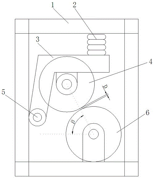
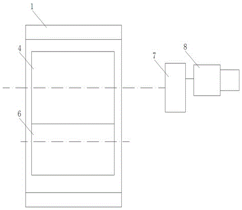
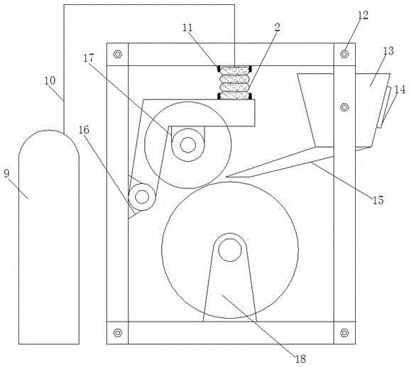
[0036] Such as Figure 1~5 As shown, it shows a specific embodiment of the present invention. As shown in the figure, a pair of roller crushing sand making machine of the present invention includes a driving roller 4 and a driven roller 6; The axes are parallel; the connecting line of the center of the same section of the active roller and the passive roller has an included angle of β with the negative direction of the X axis of the section, and 75°<β<90°; the active roller and the passive roller The distance between the closest points of the circumferential surface of the same section of the roller is D, and 0≤D≤3mm;

[0037] As shown in the figure, the two ends of the driving roller 4 and the driven roller 6 are respectively coaxially provided with end shafts, and the two ends of the driven roller are rotatably installed on the frame 1; the driving roller end shafts on both sides of the driving roller The rotation is installed on the rotary arm 3; the rotary arm is installe...


PUM


Abstract

The invention discloses an opposite roller type smashing sand making machine which comprises a driving roller and a driven roller. The axis of the driving roller and the axis of the driven roller are parallel. The included angle between the connecting lines of circle center of the driving roller and the circle center of the driven roller on the same cross section and the negative direction of the X-axis of the cross section is beta, and beta is larger than 75 degrees and smaller than 90 degrees. The distance between the nearest points of the circumferential face of the driving roller and the circumferential face of the driven roller on the same cross section is D, and D is larger than or equal to 0 and smaller than or equal to 3 mm. The two ends of the driving roller and the two ends of the driven roller are coaxially provided with end shafts, and the two ends of the driven roller are rotatably mounted on a machine frame. The driving roller end shafts on the two sides of the driving roller are rotatably mounted on rotating arms. The rotating arms are rotatably mounted on bearings of rotating bearing blocks through rotating shafts. The top ends of the rotating arms are connected to a rotating arm pressing plate which is parallel to the axis of the driving roller in the length direction of the driving roller. A pressing air bag capable of being inflated and deflated is arranged between the rotating arm pressing plate and the top of the machine frame.

Description

technical field [0001] The invention relates to a sand making machine, in particular to a crushing sand making machine comprising a driving roller and a passive roller. Background technique [0002] A sand making machine that crushes massive stones into fine sand and gravel generally includes two rollers (active roller and passive roller) whose axes are on the same horizontal plane, and the stones are crushed after passing between the two rollers. ; We found in the long-term crushing machinery design and actual use process that the existing sand making machine that crushes through two rollers has the following defects: [0003] 1. The two rollers located on the same plane generally need to design a complex structure to realize the single-drive two rollers to rotate in opposite directions; The power drives the motor, which consumes a lot of energy; [0004] 2. For some new designs, the gap between the two rollers is set to be very small, even 0, so that only one driving rol...

Claims


Application Information

Patent Timeline
IPC IPC(8): B02C4/02B02C4/30B02C4/32
CPCB02C4/02B02C4/30B02C4/32
Inventor 李小阳张少波谢俊峰
Owner 福建美斯拓机械设备有限公司
Why Eureka
Try Eureka