Collecting pipe machining process and forming equipment thereof

A technology of processing, forming and processing technology, which is applied in the field of collecting tube processing technology and its forming equipment, and can solve the problems of uneven spacing, low stamping efficiency, and affecting the clamping of louver corrugated heat sinks, etc.

Active Publication Date: 2015-10-28
ZHEJIANG CHUANGXIN AUTO AIR CONDITIONER
View PDF11 Cites 10 Cited by
  • Summary
  • Abstract
  • Description
  • Claims
  • Application Information

AI Technical Summary

Problems solved by technology

[0003] The commonly used equipment for punching header holes on the market is a group of holes that are uniformly dist

Method used


Image

  • Collecting pipe machining process and forming equipment thereof
  • Collecting pipe machining process and forming equipment thereof
  • Collecting pipe machining process and forming equipment thereof

Examples


Embodiment Construction

[0039] The present invention will be further described below in conjunction with the accompanying drawings:

[0040] Referring to the accompanying drawings: the processing technology of this header is characterized by the following steps:

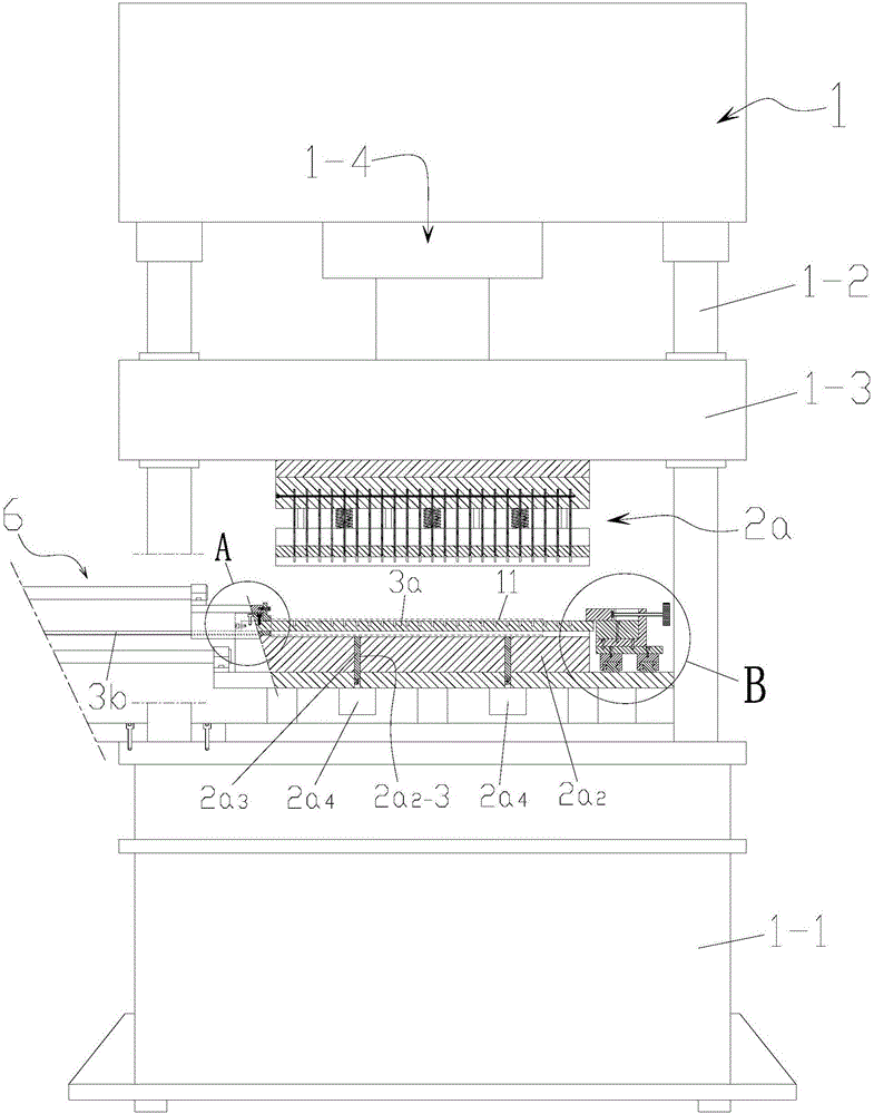
[0041] A. Loading: Insert the steel pipe 11-1 into the cylindrical rod 3a;

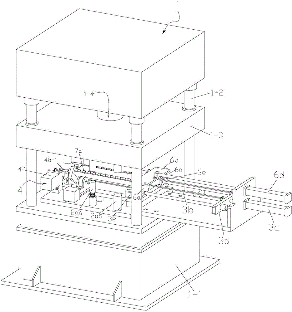
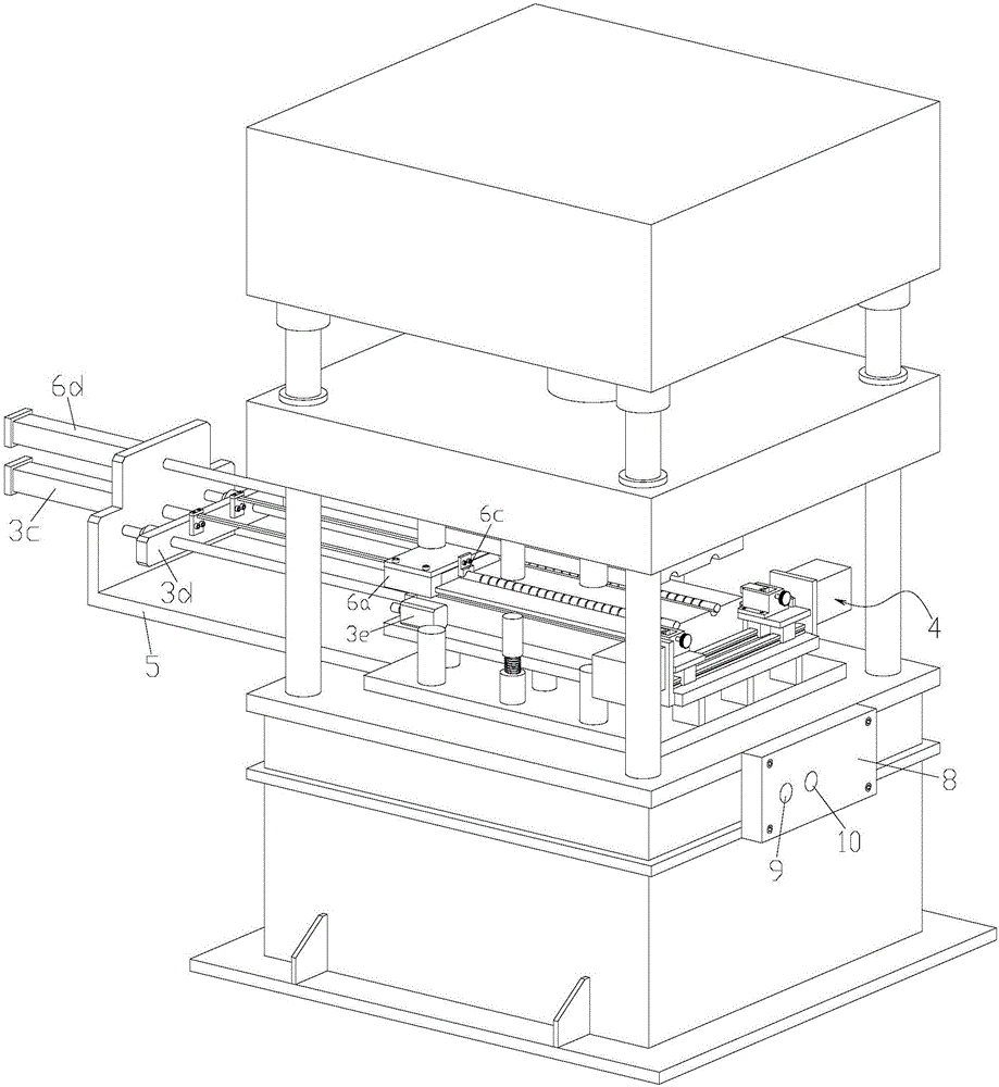
[0042] B. Clamping correction: first start the power switch 9, part of the program of the PLC controller 8 is activated, the PLC controller 8 controls the second cylinder 4f to drive the sliding block 4a to move, so that the first sliding block 4b is located above the cylindrical rod 3a, and then Manually move the end face of the steel pipe 11-1 to fit the end face of the first slider 4b, and then twist the screw block 4e used to adjust the movement of the first slider 4b, so as to adjust the steel pipe 11-1 and the punching piece 2a1- The relative position between 6 (the same batch of products only need to be adjusted once), then press the program switch 10, the ...


PUM


Abstract

Disclosed is a collecting pipe machining process. The collecting pipe machining process includes the following steps of A, loading; B, clamping and correction; C, stamping; D, tool retraction; E, material ejection; and F discharging. Collecting pipe machining and forming equipment comprises a press. The press comprises a base, guide columns fixed to the four corners of the base and a pressing block connected to the guide columns in a sliding manner. A power assembly capable of driving the pressing block to move up and down is fixed to the tops of the guide columns. A collecting pipe insertion hole stamping device is arranged below the pressing block. A collecting pipe clamping device is fixed to the side of the collecting pipe insertion hole stamping device. A collecting pipe correction device is fixed to the side of the collecting pipe clamping device. The distance between the bottom face of a first sliding block and the top end of a cylinder rod is matched and the positions of all slots are matched with the positions of all through holes. Clamping, correcting and punching of a collecting pipe are integrated, the collecting pipe is truly machined automatically and integrally, workers and equipment are reduced, operation is simple, and the process and the equipment are worthy of application and popularization.

Description

technical field [0001] The invention relates to a part processing technology and its mechanical equipment, in particular to a collecting tube processing technology and its forming equipment for punching and forming a collecting tube jack. Background technique [0002] The parallel-flow condenser is one of the three major components of the automobile air conditioning system. Therefore, in this process, making a set of evenly spaced sockets on the header is the key to ensure that the porous flat tubes can be inserted into the header sockets accurately and quickly and complete subsequent operations. [0003] The commonly used equipment for punching the header jacks on the market is a group of jacks that are uniformly punched and formed one by one. This kind of jack punching method not only has low punching efficiency, but also has different distances between the jacks, which affects the follow-up. The clamping of the louver wave fins and ultimately affects the quality of the o...

Claims


Application Information

Patent Timeline
IPC IPC(8): B21D28/28B21D28/34B21D43/00B21D45/02
CPCB21D28/28B21D28/34B21D43/003B21D45/02
Inventor 叶伟锋林有彬何登焕
Owner ZHEJIANG CHUANGXIN AUTO AIR CONDITIONER
Why Eureka
Try Eureka