Radio wave arrival state estimation system, radio wave arrival state estimation method, and program

a radio wave and estimation system technology, applied in the field of radio wave arrival state estimation system and radio wave arrival state estimation method, can solve the problems of increasing operational processing amount, difficult application of statistical techniques, and drastic increase in processing amount, so as to increase operational processing amount and increase operational processing amount.

Inactive Publication Date: 2009-05-21
NEC CORP
View PDF2 Cites 4 Cited by
  • Summary
  • Abstract
  • Description
  • Claims
  • Application Information

AI Technical Summary

Benefits of technology

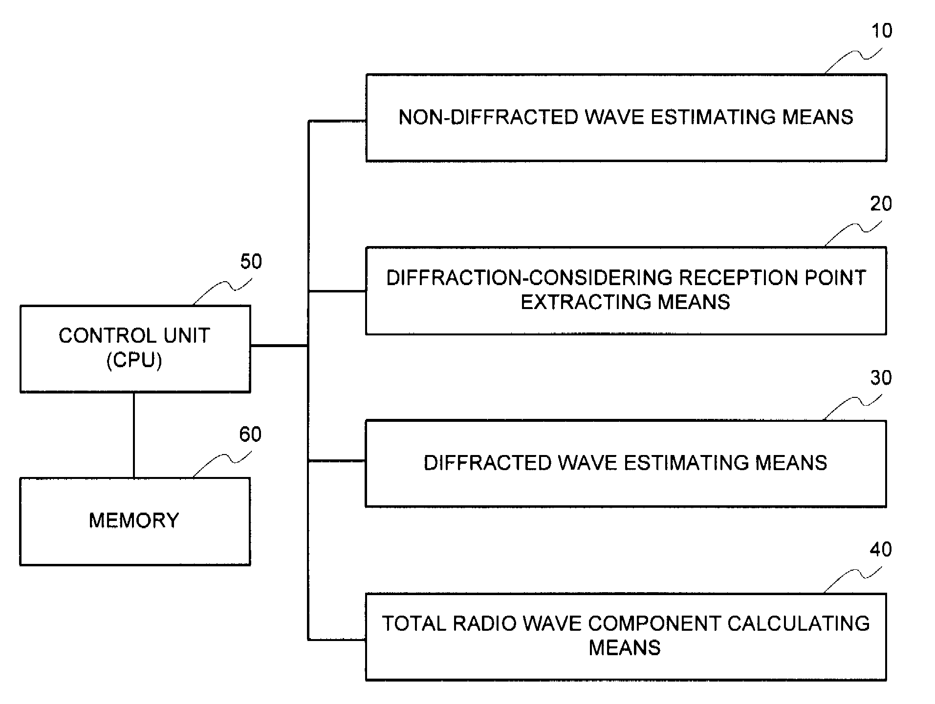
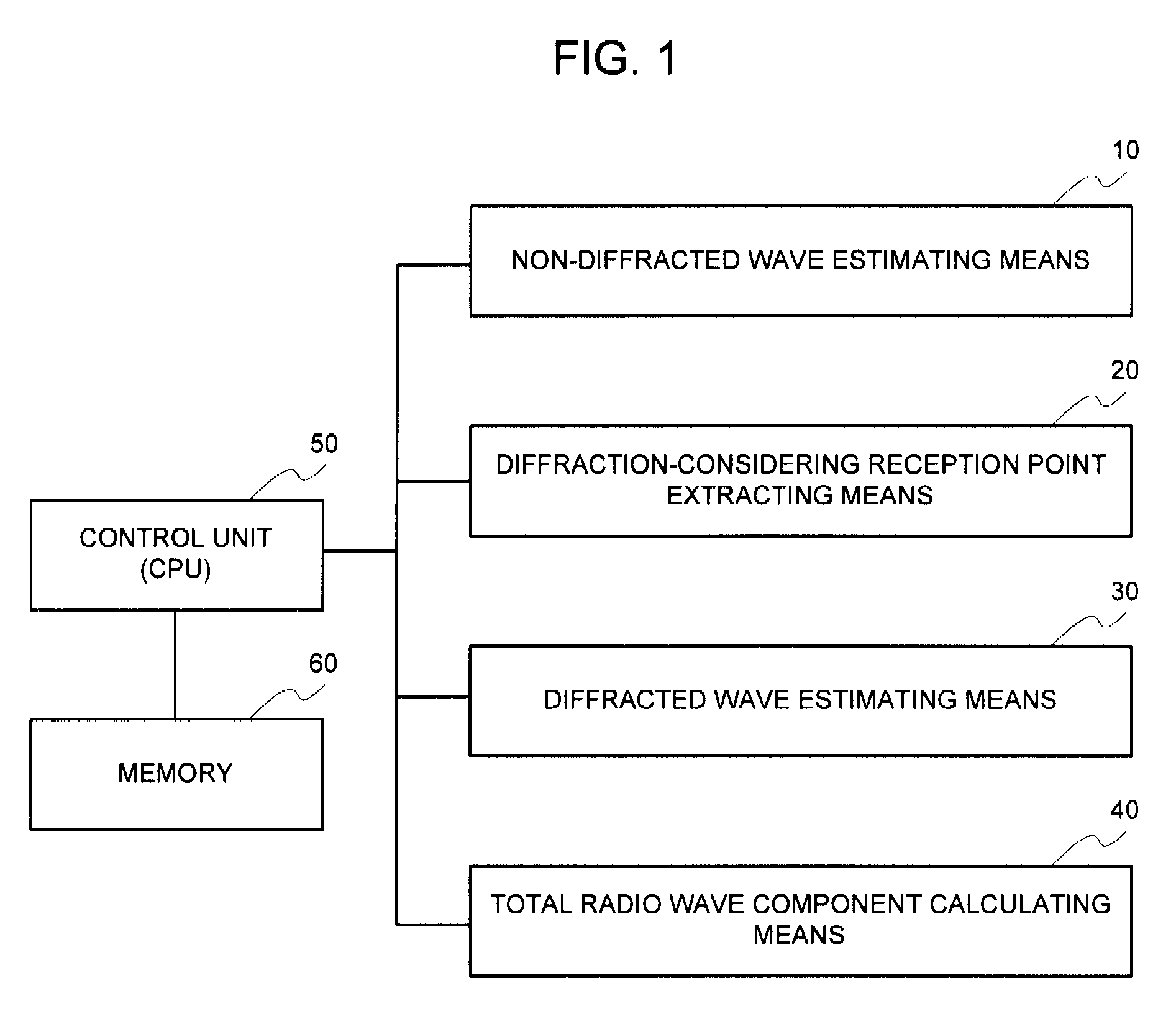
[0023]The present invention makes it possible to precisely estimate the propagation considering the diffraction without drastically increasing the operational processing amount by applying the speedy and precise radio wave propagation estimation technique for estimation of the waves other than the diffracted wave, for example, the direct wave / reflected wave / transmitted wave, and employing the radio wave propagation estimation technique having a light operation load, which is different from the estimation technique employed for estimation of the waves other than the diffracted wave, for the diffracted wave.
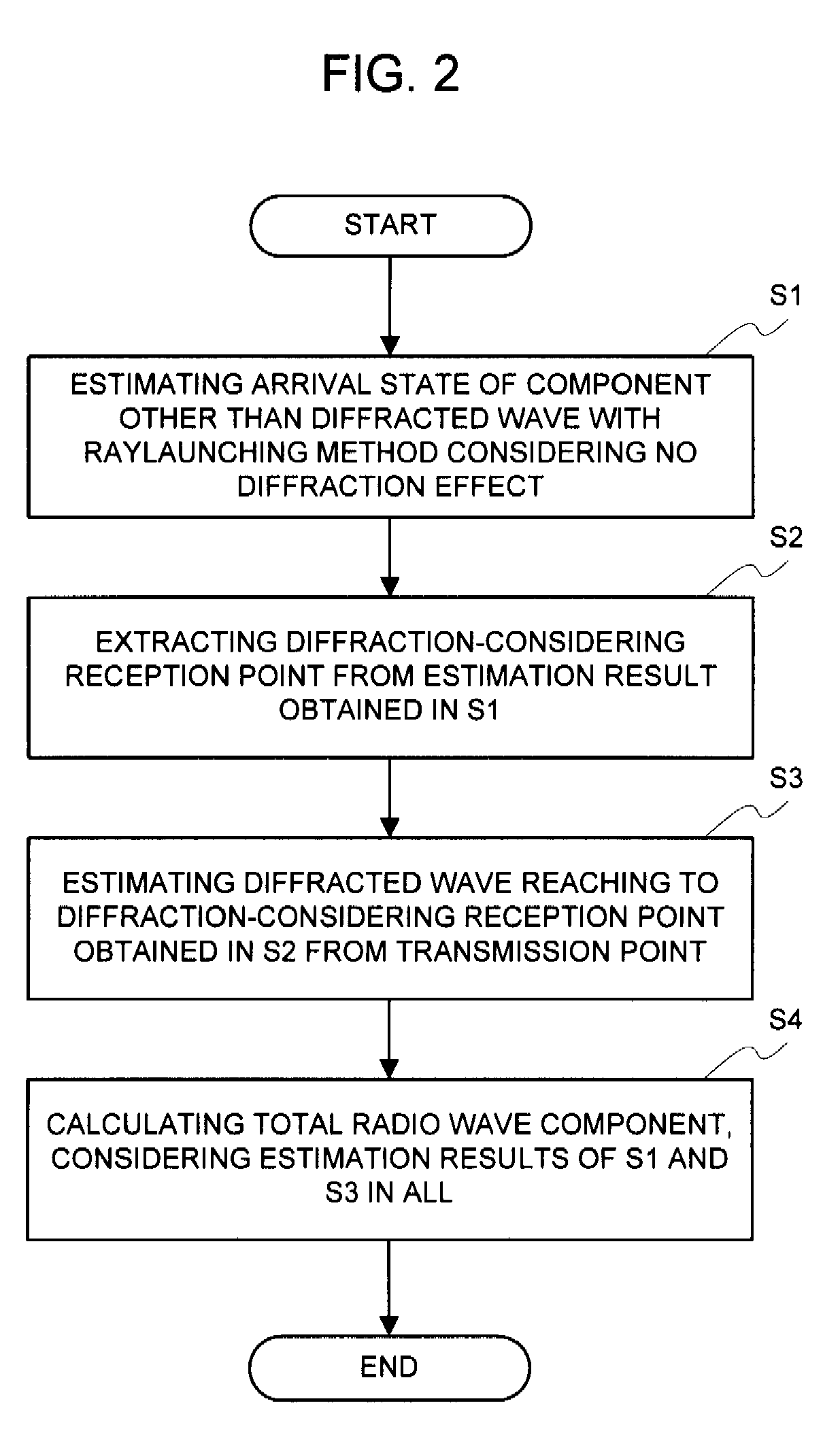
[0024]The present invention makes it possible to precisely estimate the propagation considering the diffraction without drastically increasing the operational processing amount by estimating the waves other than the diffracted wave, for example, the direct wave / reflected wave / transmitted wave, out of the radio waves that are in a state of arriving at the reception point, with the speedy and yet precise radio wave propagation estimation technique, obtaining a diffraction-considering reception point based upon this estimation result, and employing the radio wave propagation estimation technique, of which the operational load is lighter than that of the above-mentioned radio wave propagation estimation technique, for this obtained diffraction-considering reception point.

Problems solved by technology

In particular, the statistical technique is difficult to apply, and rather, the deterministic technique is desirably applied in the circumstances where a lot of the structures and objects that exert an influence upon the radio wave propagation exist, for example, in a city, in a room, or the like.
This causes the problem that the number of the rays, which should be processed with an occurrence of one-time diffraction, augments, and thus the operational processing amount augments to that extent.
However, an increase in the number of the structures that are considered, and an increase in the maximum number of times of the reflection / transmission / diffraction cause the problem that the operational processing amount augments drastically.
Further, there is the case that a sufficient reduction in the operational processing amount cannot be attained depending upon the propagation circumstances.
However, in a case of estimating the radio wave propagation characteristic in the city that is overcrowded with the buildings, almost all of the observatory points are not in prospect.
Thus, applying the imaging method for all these points inevitably increases the operational processing amount.

Method used


Image

  • Radio wave arrival state estimation system, radio wave arrival state estimation method, and program
  • Radio wave arrival state estimation system, radio wave arrival state estimation method, and program
  • Radio wave arrival state estimation system, radio wave arrival state estimation method, and program

Examples


example 1

[0051]The first example of the present invention will be explained. It is assumed that the evaluation area, and the transmission point and the reception point of the wireless system that are envisaged in this example are identical to ones shown in FIG. 3, FIG. 4 is a flowchart illustrating an operation of this example.

[0052]In this example, at first, the components other than the diffracted wave component out of the radio wave components reaching from the transmission point 100 to each reception point are estimated with the raylaunching method considering no diffraction effect (step S11). It is assumed the propagation loss at the reception point in the n-th row and the m-th column obtained herein is L1—n, m. Next, only the diffracted wave component out of the radio wave components reaching from the transmission point 100 to each reception point is estimated (step S13). The propagation estimation method different from the raylaunching method employed in the step S11 is applied for th...

example 2

[0060]The second example of the present invention will be explained. It is assumed that the evaluation area, and the transmission point and the reception point of the wireless system that are envisaged in this example are identical to ones shown in FIG. 3. FIG. 7 is a flowchart illustrating an operation of this example.

[0061]In this example, at first, the components other than the diffracted wave component out of components of the radio waves reaching from the transmission point 100 to respective reception points are estimated with the raylaunching method considering no diffraction effect (step S21). It is assumed the propagation loss at the reception point in the n-th row and the m-th column obtained herein is L1—n, m. Next, it is determined from the propagation estimation result at each reception point in the step S21 whether or not the above reception point is a diffraction-considering reception point, and the diffraction-considering reception point within the evaluation area is ...

example 3

[0071]The third example of the present invention will be explained. It is assumed that the evaluation area, and the transmission point and the reception point of the wireless system that are envisaged in this example are identical to ones shown in FIG. 3. FIG. 8 is a flowchart illustrating an operation of this example.

[0072]In this example, at first, the components other than the diffracted wave component out of components of the radio wave component reaching from the transmission point 100 to respective reception points are estimated with the raylaunching method considering no diffraction effect (step S31). It is assumed that the propagation loss at the reception point in the n-th row and the m-th column obtained herein is L1—n, m.

[0073]Next, it is determined from the propagation estimation result at each reception point in the step S31 whether or not the above reception point is a diffraction-considering reception point, and the diffraction-considering reception point within the e...


PUM


Abstract

It is possible to accurately estimate propagation considering diffraction without significantly increasing the operation processing amount. A radio wave propagation characteristic estimation system in a radio communication system includes: non-diffracted wave estimation means for estimating propagation characteristic of a radio wave reaching from a predetermined transmission point in a limited evaluation area to a plurality of reception points in the evaluation area and estimating a component other than diffracted wave among the radio wave component reaching from the transmission point to the reception points; diffracted wave estimation means for estimating only a diffracted wave component among the radio components reaching from the transmission point to the respective reception points; and total radio wave component calculation means for calculating total radio wave propagation characteristic in the respective reception points considering the estimated result in the non-diffracted wave estimation means and the estimation result of the diffracted wave estimation means.

Description

APPLICABLE FIELD IN THE INDUSTRY[0001]The present invention relates to a system for speedily estimating an effect of diffraction in a radio wave propagation characteristic (radio wave arrival state) estimation, a method thereof, and a program thereof.BACKGROUND ART[0002]A radio wave propagation characteristic estimation system (radio wave propagation simulator) is employed to assist the arrangement for a base station, a parent machine, or the like in a wireless communication system, and the optimization of parameters of the arranged base station and parent machine, or the like. The radio wave propagation simulator assesses a received power, a delay spread, or the like at an optional reception point to decide an installation side of a due transmitting station, so that the overall efficiency can be enhanced by reducing the number of the base stations to be arranged. Further, deciding an optimal parameter of the transmitting station enables a network quality of the wireless communicati...

Claims


Application Information

Patent Timeline
Patent Type & Authority Applications(United States)
IPC IPC(8): G01R29/08H04W16/18H04W24/00
CPCH04B17/3913
Inventor SUGAHARA, HIROTOMOTOYOSHI, MASAHIRO
Owner NEC CORP
Why Eureka
Try Eureka