air conditioner

A technology for air conditioners and outdoor heat exchangers, which is applied in the direction of air conditioning systems, machine operation, space heating and ventilation, etc., can solve the problems of low temperature of electronic control components, poor heat dissipation effect, and impact on user comfort, etc. To avoid excessive cooling, ensure heat dissipation, improve safety and reliability

Active Publication Date: 2017-06-09
GD MIDEA AIR CONDITIONING EQUIP CO LTD +1
View PDF4 Cites 0 Cited by
  • Summary
  • Abstract
  • Description
  • Claims
  • Application Information

AI Technical Summary

Problems solved by technology

[0002] At present, with the development of air-conditioning technology, the calorific value of the electronic control components of the air conditioner is gradually increasing. In related technologies, most of the electronic control components rely on heat sinks and air convection to complete heat dissipation, but in high-temperature environments, the heat dissipation effect is poor.
[0003] In order to maintain the normal operation of the air conditioner, manufacturers of inverter air conditioners usually solve the heating problem of the electronic control components by reducing the operating frequency of the compressor to reduce the heat generated by the electronic control components, but this method affects the performance of the air conditioner in high temperature environments When the cooling effect, affecting the comfort of the user
[0004] In the related art, there are air conditioners that use low-temperature refrigerant to dissipate heat from electronic control components, but there is a problem that the temperature of the electronic control components is too low due to excessive cooling, and even condensation water is generated, which affects the reliability and reliability of the electronic control components. safety

Method used


Image

  • air conditioner
  • air conditioner
  • air conditioner

Examples


Embodiment Construction

[0038] In order to understand the above-mentioned purpose, features and advantages of the present invention more clearly, the present invention will be further described in detail below in conjunction with the accompanying drawings and specific embodiments. It should be noted that, in the case of no conflict, the embodiments of the present application and the features in the embodiments can be combined with each other.

[0039] In the following description, many specific details are set forth in order to fully understand the present invention. However, the present invention can also be implemented in other ways different from those described here. Therefore, the protection scope of the present invention is not limited by the specific details disclosed below. EXAMPLE LIMITATIONS.

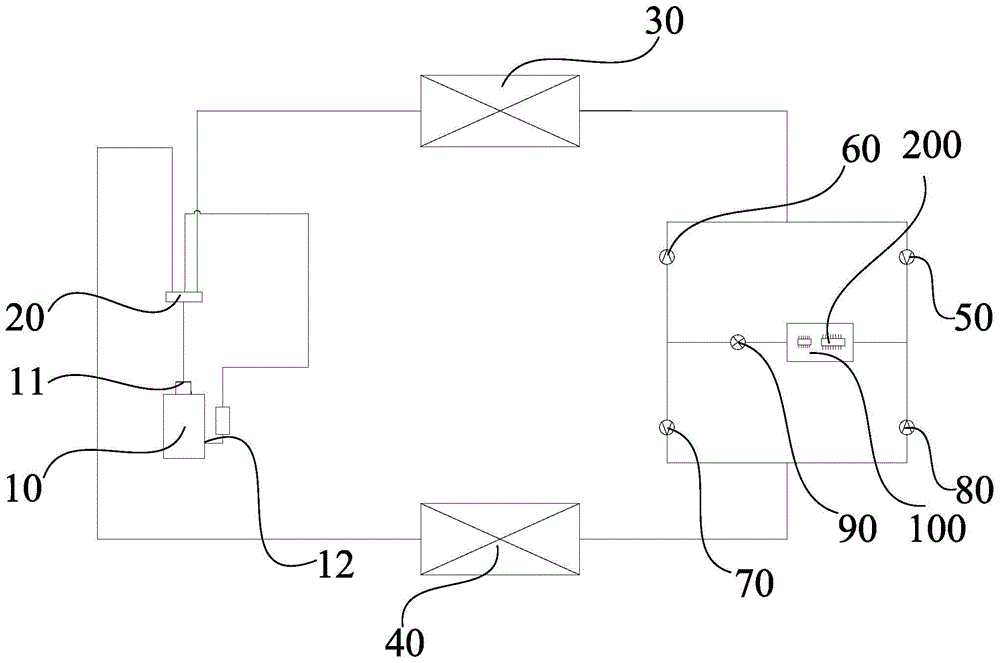
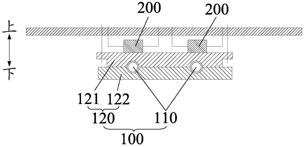
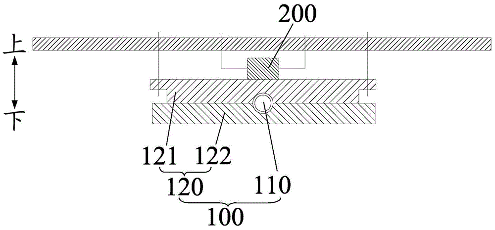
[0040] Refer below Figure 1 to Figure 5 Air conditioners according to some embodiments of the present invention are described.

[0041] Such as figure 1 , Figure 4 and Figure 5 As shown, the ...


PUM


Abstract

The present invention provides an air conditioner, comprising: a compressor, a four-way valve, an outdoor heat exchanger, an indoor heat exchanger, and first, second, third and fourth unit directional conduction device, throttling device, cooling assembly and electric controller, the inlet of the first unidirectional conduction device and the outlet of the second unidirectional conduction device communicate with the same port of the outdoor heat exchanger; the outlet of the third unidirectional conduction device The inlet of the fourth unidirectional conduction device communicates with the same port of the indoor heat exchanger; the outlet of the first unidirectional conduction device and the outlet of the fourth unidirectional conduction device communicate with the inlet of the heat dissipation assembly through the second pipeline; the heat dissipation assembly The outlet communicates with the inlet of the throttling device; the inlet of the second unidirectional conduction device and the inlet of the third unidirectional conduction device communicate with the outlet of the cooling assembly through the first pipe. The air conditioner provided by the present invention uses a medium-temperature refrigerant to dissipate heat from the electric controller, which not only ensures the heat dissipation effect, but also avoids excessive cooling to produce condensed water.

Description

technical field [0001] The present invention relates to the technical field of household appliances, in particular to an air conditioner. Background technique [0002] At present, with the development of air-conditioning technology, the calorific value of the electronic control components of the air conditioner is gradually increasing. In related technologies, most of the electronic control components rely on heat sinks and air convection to complete heat dissipation, but in high-temperature environments, the heat dissipation effect is poor. . [0003] In order to maintain the normal operation of the air conditioner, manufacturers of inverter air conditioners usually solve the heating problem of the electronic control components by reducing the operating frequency of the compressor to reduce the heat generated by the electronic control components, but this method affects the performance of the air conditioner in high temperature environments The cooling effect at the time a...

Claims


Application Information

Patent Timeline
Patent Type & Authority Patents(China)
IPC IPC(8): F25B13/00F25B29/00F25B41/04F25B49/02F24F1/24F25B41/20
CPCF24F1/0003F24F1/24
Inventor 孟庆好
Owner GD MIDEA AIR CONDITIONING EQUIP CO LTD
Why Eureka
Try Eureka