
Method for automatic resistance adjustment of foil resistance strain gauge and automatic resistance adjustment equipment

A resistance strain gage and strain gage technology, applied in non-electric variable control, control/regulation systems, instruments, etc., can solve the problem of inability to accurately measure the real resistance value of the strain gage in real time, the adjustment amount of the resistance value that cannot be controlled, and the strain gage. Sensitive quality has a great impact, achieving the effect of batching, ensuring positioning accuracy and repeatability, and reducing the difficulty of operation

Active Publication Date: 2018-02-23
王晓冉
View PDF5 Cites 0 Cited by
  • Summary
  • Abstract
  • Description
  • Claims
  • Application Information

AI Technical Summary

Problems solved by technology

[0010] In order to overcome the above-mentioned problems of low resistance adjustment efficiency, high labor intensity, human factors in the processing process that have a great influence on the sensitive quality of the strain gauge, and the method of automatic resistance adjustment of the electrochemical corrosion strain gauge causes the corrosion liquid to flow into the measurement On the probe, the measurement accuracy of the resistance value is seriously affected, and the real resistance value of the strain gauge cannot be measured accurately and in real time, so that the adjustment amount of the resistance value cannot be controlled. The invention provides an automatic resistance adjustment for the foil resistance strain gauge method, including the following steps:

Method used


Image

  • Method for automatic resistance adjustment of foil resistance strain gauge and automatic resistance adjustment equipment
  • Method for automatic resistance adjustment of foil resistance strain gauge and automatic resistance adjustment equipment
  • Method for automatic resistance adjustment of foil resistance strain gauge and automatic resistance adjustment equipment

Examples


Embodiment Construction

[0044] The present invention will be further described below with reference to the accompanying drawings.

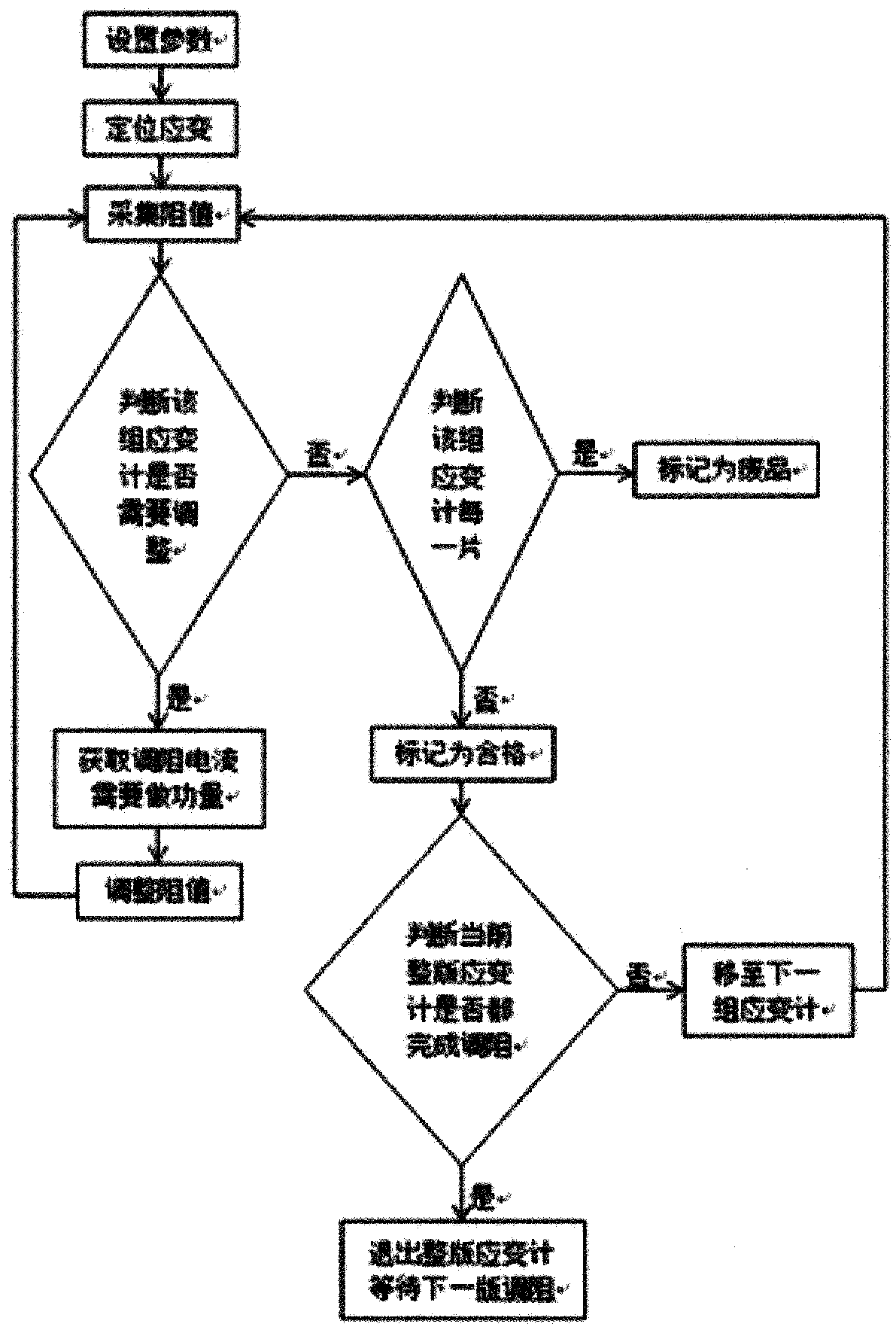
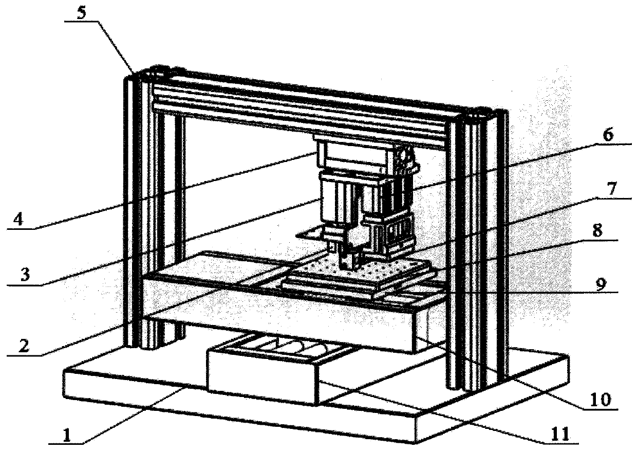
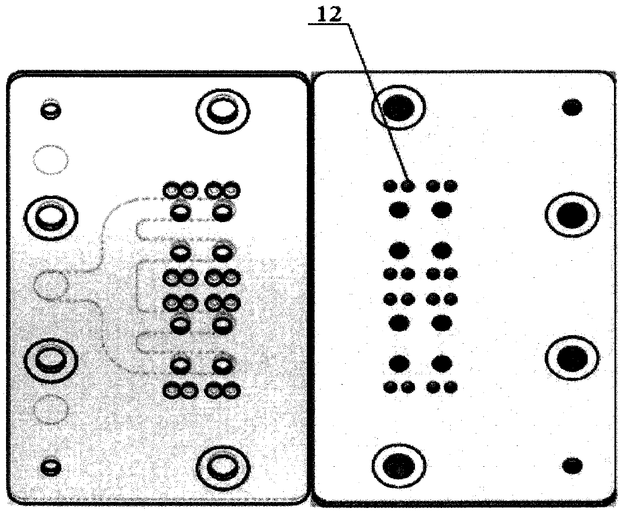
[0045] refer to figure 1 , 2 , 3, 4, the method for automatically adjusting the resistance of the foil resistance strain gauge provided by the present invention includes the following steps:

[0046] Parameter setting: Set the resistance adjustment parameters of the foil resistance strain gauge according to different types of foil resistance strain gauges and different requirements, calibrate according to the displacement deviation of the mechanical structure, set the calibration parameters of the mechanical structure, and set the calibration parameters according to the foil resistance strain gauge. Set the type parameters of the type resistance strain gauge;

[0047] Automatic positioning: use a punching machine to automatically identify the positioning points reserved by the foil resistance strain gauge, make two positioning mark round holes on the two positioning m...


PUM


Abstract

The invention relates to a method for automatically adjusting resistance of a foil-type resistance strain gauge; it mainly comprises thinning the wire grid of the foil-type resistance strain gauge according to a reverse electroplating method; Accurately find out the amount of work that the resistance strain gage needs to adjust the resistance current; during the measurement process, the actual resistance value of the strain gage to be adjusted is obtained by comparing the resistance strain gage to be adjusted with the standard resistance set in the measurement current; through I‑ The V-F conversion method can accurately obtain the actual power of the resistance strain gauge to be adjusted at the current current; the invention also relates to an automatic resistance adjustment device implementing the automatic resistance adjustment method. Through the invention, the stability, uniformity and accuracy of the resistance value of the product are improved, the resistance regulation efficiency of the product is improved, and the labor cost is reduced.

Description

technical field [0001] The invention relates to a method for automatic resistance adjustment of foil resistance strain gauges, wherein a reverse electroplating method is used in the automatic resistance adjustment method; Automatic resistance adjustment equipment for the method of resistance adjustment. Background technique [0002] A resistance strain gauge (hereinafter referred to as a strain gauge) is a sensitive element that utilizes the principle of "resistance-strain", and the pattern structure unit of the strain gauge is usually formed by processes such as substrate preparation, exposure, and corrosion. Due to the foil rolling and strain gauge manufacturing errors, the thickness and width of the sensitive grid will be dispersed in microns to nanometers. After the strain gauge is corroded and formed, the resistance value cannot all reach the nominal resistance value. Directly used for test measurement. In order to ensure that the resistance value of the strain gauge ...

Claims


Application Information

Patent Timeline
Patent Type & Authority Patents(China)
IPC IPC(8): G05D5/03
Inventor 不公告发明人
Owner 王晓冉
Learn More