

Fingerprint identification method and device
A fingerprint identification and fingerprint technology, which is applied in the field of information security, can solve the problems of low identification efficiency and achieve the effect of improving the efficiency of fingerprint identification
- Summary
- Abstract
- Description
- Claims
- Application Information
AI Technical Summary
Problems solved by technology
Method used
Image

Examples
Embodiment 1
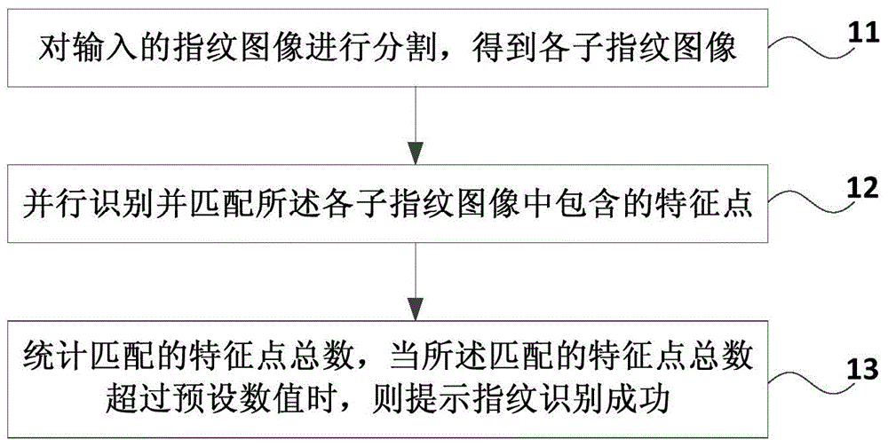
[0022] figure 1 It is a schematic flow chart of the fingerprint recognition method provided in Embodiment 1 of the present invention, as shown in figure 1 shown, including:
[0023] Step 11, segmenting the input fingerprint image to obtain each sub-fingerprint image;
[0024] For example, in order to improve the recognition speed of the fingerprint image in the embodiment of the present invention, the fingerprint image may be divided in advance to obtain sub-fingerprint images. The specific division principle can be determined according to the configuration of the execution subject. If the execution subject of the embodiment of the present invention is configured with a multi-processor, multi-core processor, chip-level multi-processing or simultaneous multi-thread processor, it can be divided according to the processing capabilities of the above-mentioned processors or processors, or evenly divided fingerprint image.
[0025] Step 12, identifying and matching the feature p...
Embodiment 2
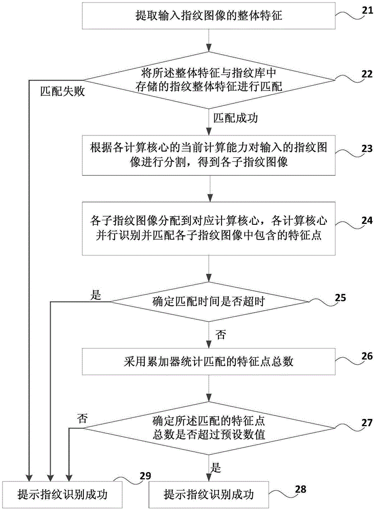
[0048] figure 2 It is a schematic flow chart of the fingerprint identification method provided by Embodiment 2 of the present invention. This embodiment uses a specific embodiment to describe the technical solution of the present invention in detail, as shown in figure 2 shown, including:
[0049] Step 21, extracting the overall feature of the input fingerprint image;
[0050] Wherein, the integral feature includes one of circular, arcuate and helical.
[0051] Step 22, matching the overall feature with the overall feature of the fingerprint stored in the fingerprint library;
[0052] If the matching is successful, go to step 23; otherwise, go to step 29.
[0053] Step 23. Segment the input fingerprint image according to the current computing capability of each computing core to obtain each sub-fingerprint image;
[0054] Step 24, each sub-fingerprint image is assigned to a corresponding computing core, and each computing core identifies and matches the feature points co...
Embodiment 3
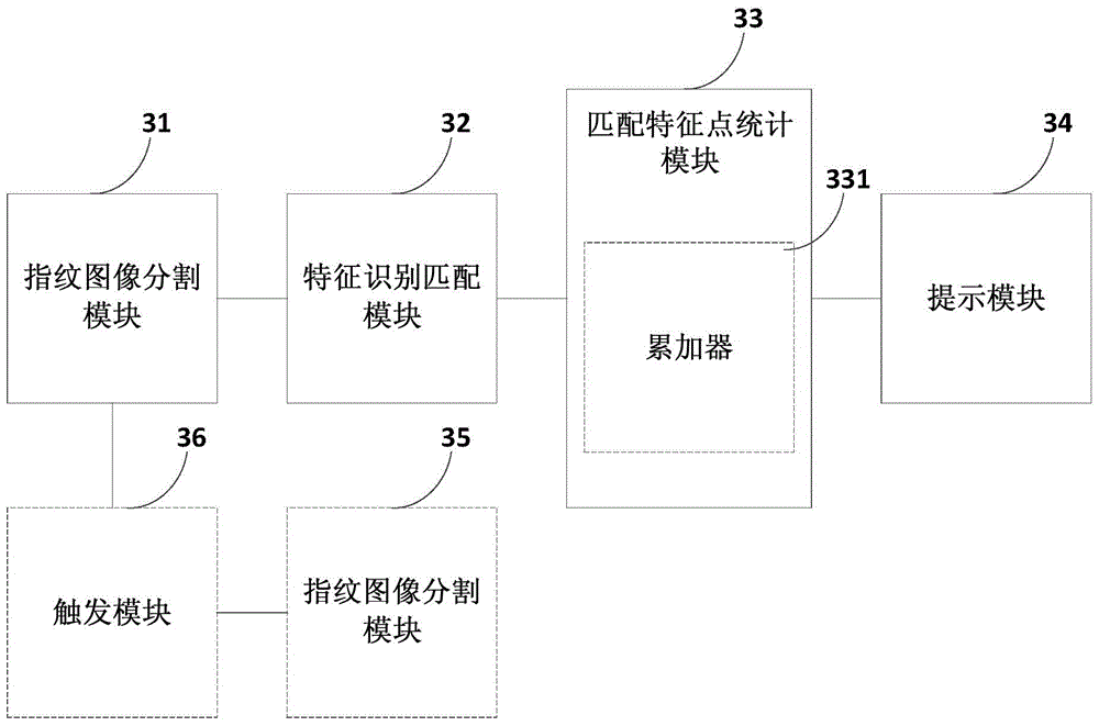
[0065] image 3 A schematic structural diagram of the fingerprint recognition device provided in Embodiment 3 of the present invention, as shown in image 3 As shown, it specifically includes: a fingerprint image segmentation module 31, a feature recognition matching module 32, a matching feature point statistics module 33 and a prompt module 34;
[0066] The fingerprint image segmentation module 31 is used to segment the input fingerprint image to obtain each sub-fingerprint image;
[0067] The feature identification and matching module 32 is used to identify and match feature points contained in each sub-fingerprint image in parallel;
[0068] The matching feature point statistics module 33 is used to count the total number of feature points matched;
[0069] The prompting module 34 is used to prompt that the fingerprint identification is successful when the total number of matching feature points obtained by the matching feature point statistics module 33 exceeds a preset...
PUM
 Abstract
Description
Claims
Application Information