A method, system and device for measuring channel state information
What is AI technical title?
AI technical title is built by Patsnap AI team. It summarizes the technical point description of the patent document.
A technology of channel state information and user equipment, applied in transmission systems, radio transmission systems, diversity/multi-antenna systems, etc., can solve problems such as time-frequency resource overhead, reduce overhead, improve resource utilization and system performance Effect
Active Publication Date: 2017-09-29
DATANG MOBILE COMM EQUIP CO LTD
View PDF3 Cites 0 Cited by
Summary
Abstract
Description
Claims
Application Information
AI Technical Summary
This helps you quickly interpret patents by identifying the three key elements:
Problems solved by technology
Method used
Benefits of technology
Problems solved by technology
[0006] The present invention provides a method, system and equipment for channel state information measurement, which are used to solve the problem existing in the prior art that under the premise of giving full play to the performance advantages of Massive MIMO, the current mechanism based on downlink reference signal measurement and feedback CSI will bring Significant time-frequency resource overhead issues
Method used
Image
Click on the blue label to locate the original text in one second.
Reading with bidirectional positioning of images and text.
Examples
Embodiment 7
[0157] Such as Figure 7 As shown, the method for measuring channel state information in Embodiment 7 of the present invention includes:
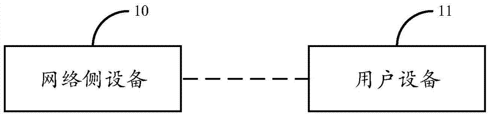
[0158] Step 701, the network side device sends a set of beamformed reference signals to the user equipment, so that the user equipment can measure the reference signals, wherein each reference signal in the set of reference signals corresponds to a space in a sector;
[0159] Step 702, the network side device judges whether to adjust the shaping mode of the reference signal according to the information fed back by the user equipment.
[0160] Preferably, each reference signal in a sector corresponds to a different channel state information measurement reference signal CSI-RS configuration and / or a different CSI-RS port.
[0161] Preferably, each reference signal in a sector corresponds to a different identifier.
[0162] Preferably, the network side device judges whether to adjust the shaping mode of the reference signal according to the ...
Embodiment 8
[0175] Such as Figure 8 As shown, the eight-channel state information measurement method of the embodiment of the present invention includes:
[0176] Step 801, the user equipment measures a set of beamformed reference signals received from the network side equipment, where each reference signal in a set of reference signals corresponds to a space in a sector;
[0177] Step 802, the user equipment feeds back information to the network side device according to the measurement result, so that the network side device judges whether to adjust the shaping mode of the reference signal according to the fed back information.
[0178] Preferably, the information fed back by the user equipment to the network side equipment according to the measurement results includes:
[0179] The user equipment feeds back the identification of the reference signal for measurement and the corresponding quality information to the network side equipment.
[0180] Preferably, the information fed back b...
PUM
Abstract
The embodiment of the present invention relates to the field of wireless communication technology, and in particular to a method, system and device for channel state information measurement, which are used to solve the problem existing in the prior art under the premise of giving full play to the performance advantages of Massive MIMO. Mechanisms for measuring and feeding back CSI will bring significant time-frequency resource overhead. A method for measuring channel state information provided by an embodiment of the present invention includes: a network side device sends a set of beamformed reference signals to a user equipment, so that the user equipment can measure the reference signals, wherein the set of reference signals Each reference signal corresponds to a space in the sector; the network side device judges whether to adjust the shaping mode of the reference signal according to the information fed back by the user equipment. The solution of the embodiment of the present invention reduces the overhead caused by downlink reference signal measurement and feedback under the premise of ensuring the performance advantage of Massive MIMO.
Description
technical field [0001] The present invention relates to the technical field of wireless communication, in particular to a method, system and equipment for measuring channel state information. Background technique [0002] In view of the important role of MIMO (Multiple Input Multiple Output) technology in improving peak rate and system spectrum utilization, LTE (Long Term Evolution, long-term evolution) / LTE-A (LTE-Advanced, long-term evolution upgrade) etc. Wireless access technology standards are all built on the basis of MIMO+OFDM (Orthogonal Frequency Division Multiplexing) technology. The performance gain of MIMO technology comes from the spatial freedom obtained by multi-antenna systems. Therefore, one of the most important evolution directions of MIMO technology in the standardization development process is the expansion of dimensions. In LTE Rel (version)-8, up to 4 layers of MIMO transmission can be supported. Rel-9 focuses on enhancing MU-MIMO technology. TM (Tran...
Claims
Application Information
Patent Timeline
Application Date:The date an application was filed.
Publication Date:The date a patent or application was officially published.
First Publication Date:The earliest publication date of a patent with the same application number.
Issue Date:Publication date of the patent grant document.
PCT Entry Date:The Entry date of PCT National Phase.
Estimated Expiry Date:The statutory expiry date of a patent right according to the Patent Law, and it is the longest term of protection that the patent right can achieve without the termination of the patent right due to other reasons(Term extension factor has been taken into account ).
Invalid Date:Actual expiry date is based on effective date or publication date of legal transaction data of invalid patent.

